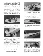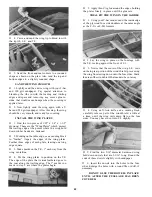
D 7. With a razor saw, cut off the ends of the tapered
trailing edges even with the tip ribs.
INSTALL TRAILING EDGE, AILERONS
AND TORQUE RODS (WING B ONLY)
Note: The following 27 steps apply to wing B
(with ailerons). If you are building wing A, skip to
the next section now.
D 1. Find the two tapered balsa T.E. (trailing edge)
pieces. They are 1-3/16" wide and 30" long.
D 2. Place one of the T.E. pieces against the rear
edge of the right wing panel on a flat surface. If there
is a 3/32" gap along the top edge, that means the T.E.
is upside down. If so, turn it over.
D 3. Just below the right wing drawing (on the
plan), there is a separate drawing showing the aileron
details. Using this drawing as a guide, cut the tapered
T.E. into three parts. Label these parts: "Rt. inboard
T.E.", "Rt. Aileron" and "Rt. outboard T.E."
("Rt." is an abbreviation for "right".)
D 4. Glue the Rt. outboard T.E. piece to the rear
edge of the right wing panel. The outer edge of the
T.E should be even with the tip as shown on the plan.
There are several ways to accomplish this, so
you may choose one of these:
A- File the groove with an 1/8" or 5/32" diameter
round file, available at hardware stores (this type
of file is normally used to sharpen small chain saw
teeth).
B- Cut the groove with a 5/32" outside diameter
brass tube. You can sharpen the tube by cutting
around the inside of one end with an X-Acto knife.
C- Cut the groove by running the T.E. piece
over a small table saw, with the blade set at the
height needed to cut a groove 5/32" deep.
D- Rout the groove out with a Dremel Moto
Tool and a 1/8" bit.
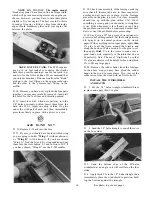
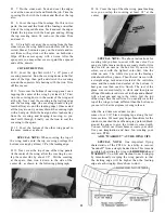
D 7. Turn the two inboard T.E. pieces upside down
as shown in the following photo, and measure 7/16"
out from the "wing centerline". At the 7/16" point,
cut a notch in both pieces with an X-Acto knife, pro-
viding free movement for the threaded portion of the
aileron torque rods.
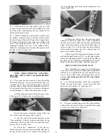
D 8. Roughen the surface of the nylon torque rod
bearings using a piece of 100 grit sandpaper.
D 9. Slide the nylon torque rod bearings as far as
they will go toward the threaded portion of the torque
rods.
D 10. With a toothpick, apply a small amount of
petroleum jelly (Vaseline, etc.) around the torque rod
where it enters the nylon bearing. This will help
prevent any excess glue from getting in and possibly
"locking up" the torque rod.
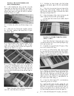
D 11. Place the torque rods into the grooved T.E.
pieces.
D 5. Repeat steps 1-4 for the left side, making the
"Lt. inboard T.E.", "Lt. Aileron" and "Lt. outboard
T.E." ("Lt." is an abbreviation for "left".)
D 6. Find the "aileron torque rods". You will
notice that there is a black nylon tube on each of the
bent rods. This nylon tube is called the "torque rod
bearing". You must now make a groove in the front
edge of each inboard T.E., so the torque rod bearing
may fit into the groove.
STOP! AT THIS POINT YOU MUST CARE-
FULLY STUDY THE PLANS AND PHOTOS TO
MAKE SURE YOU HAVE THE RIGHT TORQUE
ROD IN THE RT. INBOARD T.E., AND THE
LEFT TORQUE ROD IN THE LT. INBOARD T.E.
THE THREADED PORTION MUST COME OUT
THE BOTTOM, AND THE SHORT BENT END
MUST POINT TOWARD THE REAR.
20


