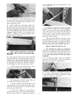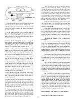
D 43. Find the two small white nylon aileron clevis
connectors and screw them about halfway onto the
threaded aileron torque rods.
D 44. Screw the two white nylon clevises onto the
threaded pushrod wires that do not have clevises
attached. Screw them on 12 turns, which is halfway.
D 45. Bend the aileron pushrods to match the pat-
terns shown in the "BOTTOM OF WING" detail on
the wing plan.
D 46. Attach the nylon clevises to the clevis connec-
tors.
SPECIAL NOTE: To insure adequate roll
(aileron) control at low speeds, it is necessary to set
up the aileron pushrod linkage so the ailerons move
upward a lot more than downward. This is called
"differential throw". If you study the "BOTTOM
OF WING" details you will see how this is ac-
complished. You must use a large servo wheel, and
attach the pushrods off-center, as shown in the draw-
ing.
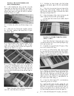
D 47. Drill two 5/64" holes in your large servo wheel,
about 45 degrees off- center. The Futaba large servo
wheel has lines that radiate out from the center every
45 degrees.
D 48. With the servo wheel and the ailerons cen-
tered, hold the aileron pushrods in place over the
holes in the servo wheel, and mark the hole locations
on the pushrods using an indelible marker.
D 49. Remove the pushrods and make Z-bends at
the marks you just made.
D 50. Re-install the aileron pushrods, work the Z-
bends into the servo wheel, hook up the aileron servo
to the receiver using the aileron extension cord
provided with your radio system, and check the oper-
ation of the ailerons.
BALANCE THE AIRPLANE LATERALLY
SPECIAL NOTE: Do not confuse this pro-
cedure with "checking the C.G." or "balancing
the airplane fore and aft". That very important
step will be covered later in the manual.
Now that you have the basic airframe nearly
completed, this is a good time to balance the airplane
laterally (side-to-side). Here is how to do it:
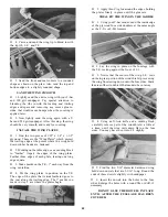
D 1. Temporarily insert the wing hold down dowels
into the fuselage, and attach the wing with about
four #64 rubber bands.
D 2. Start with the fuselage resting on a level table
with the nose gear off one edge of the table.
D 3. Grasp the propeller shaft of the engine and
lift, so the airplane is being supported only by the
propeller shaft and the bottom of the rudder. Do this
several times.
D 4. If one wing tip always drops when you lift, it
means that side is heavy. Balance the airplane by
adding weight to the inside edge of the other wing
tip rib. A good way to add weight to the tip is by
sticking several small nails (brads) or tacks into the
tip rib, from the inside. Add only a few nails or tacks
at a time, securing each one with a drop of thin CA
then re-checking the balance.
Note: In preparation for the next part, remove
all pushrods, all radio equipment (excepting the
switch), nose gear bearing, nylon aileron clevis con-
nectors, nylon rudder and elevator horns, engine, rud-
der, elevator, ailerons and all hinges. Before remov-
ing, you may wish to pre-mark any parts that may
cause confusion when re-assembling them later.
ADD THE FUSELAGE TOP
D 1. With your T-bar and 100 grit sandpaper, sand
the top of the fuse sides, upper lockplates and the
formers smooth and flat.
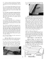
D 2. Lay the pre- shaped 1/8" balsa fuse top in
place against the front of the stab. The front edge of
the fuse top must be even with the front edge of F-3.
If not, cut or sand a small amount off the rear edge
of the fuse top. Continue cutting and checking until
the fuse top is the correct length.
D 3. Mix up some 5 minute epoxy and apply it to
the tops of F-4 and F-5 only. Immediately lay the
fuse top in place and apply thin CA glue all around
29 the edges.

