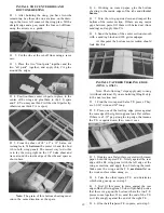
D 11. Cut a hole in the center of the fuse top, about
2" behind the wing saddle, and glue in a 2-1/2" length
of fuel tubing to serve as an antenna exit (see the
fuse plan).
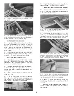
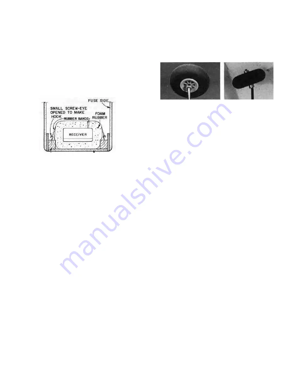
D 12. Wrap foam rubber around the receiver and
hold the foam in place with a couple of rubber bands.
Now you must attach the receiver to the fuselage in
such a way that it does not move around, but at the
same time it must be cushioned from vibration. A
good method for accomplishing this is to secure two
hooks down in the bottom corners of the fuselage,
and rubber band the receiver down.
RECEIVER (AND
BATTERY) MOUNTING
-BASSWOOD BLOCK BOTTOM
(SCRAP FROM WING SPAR)
D 13. Wrap the battery pack in foam rubber, place
it in a plastic bag, and close it with a couple of small
rubber bands. Now secure the battery pack in the
bottom of the fuel tank compartment in the same
manner as you did the receiver. Also place a piece of
foam rubber between F-l and the battery pack.
D 14. From scraps of plastic, make the "antenna st-
rain relief and the "antenna clip" (unless your radio
system includes these). Pass the receiver antenna
wire through the holes in the plastic strain relief
piece, then through the antenna exit tube. Adjust
the position of the strain relief such that the portion
of the antenna inside the fuselage remains loose,
even when you pull on the end of the antenna. Now
attach the end of the antenna to the top of the fin
using your antenna clip, a small rubber band and a
pin. Note: The receiver antenna is "tuned" for the
frequency on which the radio will operate, so do not
cut off any of its length. Just allow the excess to trail
behind.
D 15. Plug the servo wires into the receiver and hook
up the battery and switch (refer to your radio instruc-
tion manual for guidance).
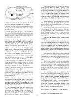
D 16. The fuse top view shows a piece of 1/16" wire
passing through the switch and out the side of the
fuse. This enables you to switch the receiver on and
off without removing the wing. Install a remote on/off
switch pushrod similar to the one shown.
D 17. Lay the fuel tank in place on top of the battery
pack. Run a piece of fuel line tubing from the fuel
pick-up ("klunk") through the hole in F-l to the fit-
ting on the carburetor. Run a second piece of tubing
from the tank "vent" through the hole in F-l to the
pressure tap fitting on the muffler. To prevent fuel
foaming the tank must be isolated from direct con-
tact with the fuselage, so add foam rubber in front
and on top of the tank before replacing the hatch.
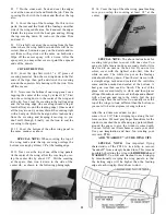
D 18. Install the wheels on the main landing gear
and nose gear using 5/32" wheel collars on both sides
of each wheel
SPECIAL NOTE: If you plan to f l y from a
concrete, blacktop or smooth grass field, use 2-1/2"
diameter main wheels and a 2-1/4" diameter nose
wheel. However, if the field you will be flying from
is rough or has fairly long grass, we recommend using
2-3/4" main wheels and a 2-1/2" nose wheel. In either
case, you should bend the main landing gear if neces-
sary so the model sits level or slightly nose down
when at rest.
D 19. Install the proper size propeller for your engine
(see your engine instruction manual), and a 2-1/4"
diameter spinner. Note: If you choose not to use a
spinner, you should ( for safety reasons) use a rounded
"acorn"-type prop nut to hold the propeller on.
SPECIAL NOTES ON PROPELLERS: Vib-
ration is the main enemy of the electronic and
mechanical parts in an R/C airplane, and an out-of-
balance propeller is the primary source of the hard
vibrations that cause problems. For only a few dollars
you may purchase a prop balancer. We highly recom-
mend that you do so, and carefully balance each prop-
eller before bolting it on your airplane.
Always use propellers that are in perfect shape.
Discard any prop with nicks, scratches, splits or
cracks or any sign of wear and damage. Never repair
or alter a prop (propeller).
Paint the prop tips white so you can see the
ends when the prop is spinning (this is especially
important if you are using one of the black fiberglass-
filled nylon props).
Install the prop with the curved side facing
forward. Securely tighten the prop nut. Inspect the
prop and re-tighten the nut after every few flights.
If you install a spinner, make sure the edges of the
spinner do not touch the prop blades.
D 20. While standing behind the model, adjust
the servo reversing switches on your transmitter so
the elevator, rudder, throttle (and ailerons) move in
the correct directions as follows:
33

