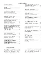
The 4-Channel version has more ability to per-
form acrobatic maneuvers, but is more difficult to
build and its self-recovery characteristics are not
quite as good. If you already have some R/C flying
experience and are ready to move up to an airplane
that is more maneuverable, you may choose to build
your PT40 as a 4-Channel airplane with Wing B.
BUILD THE FUSELAGE SIDES
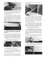
D 1. Take the two large 1/8" balsa fuselage sides
and put them together. Carefully line them up along
the bottom edge and the front. Tape them together
with a few pieces of masking tape along the bottom
edge to prevent them from moving. Now examine the
other edges to make sure the two fuselage sides are
exactly the same all around. If not, use a T-bar sander
with 100 grit sandpaper to lightly sand the edges to
match.
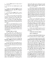
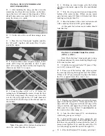
D 2. Now, with the tape still in place along the
bottom edge, let the two sides fall open and write
"Rt inside" and "Left inside" as shown here.
D 3. Tape the fuselage plan to your building sur-
face.
D 4. Lay the right fuse (fuselage) side on the plan,
and carefully position it so the bottom edge and the
nose line up with the plan. Insert a few pins or tape
to hold it in place.
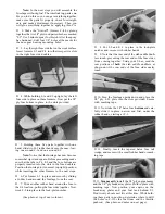
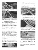
D 5. Using the "locator arrows", a straightedge
and a pen, draw six vertical lines on the fuse side as
shown. Press lightly to avoid damaging the balsa.
D 8. Now draw lines on the left inside fuse side,
using the edge marks and a straight edge.
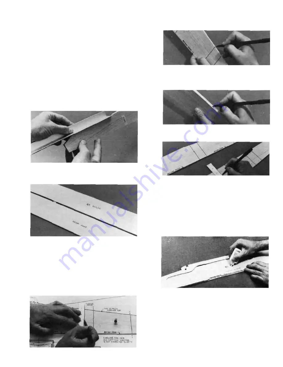
D 6. Remove the fuse side from the plan and make
small marks on the top and bottom edges, where the
lines end.
D 7. Put the two fuse sides together (inside to in-
side), and line them up carefully. While holding them
together, transfer the edge marks over to the left fuse
side edges as shown here.
D 9. Lay the large 1/8" ply fuse doubler on the right
inside fuse side and position it to line up at the nose
and bottom edge. The part of the doubler which is
behind the L.G. plate area must be exactly 1/8"
above the bottom edge of the fuse side. Use a piece
of 1/8" balsa (such as the "windshield" piece) to check
this spacing. When you are satisfied that the doubler
is correctly lined up, apply thin CA glue all around
the edges while holding the doubler in place. Use
enough glue to make sure it flows under the plywood
to make a good bond.
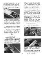
D 10. Position the upper and lower "lock plates" and
the stab saddle doublers on the right fuse side, using
the vertical guidelines previously drawn. The upper
lock plates and stab saddle doubler must be even with
the top edge of the fuse side. The three lower
lock plates must be positioned 1/8" above the bot-
tom edge of the fuse side. Use a piece of 1/8" balsa
as a spacer to aid in correct positioning of the bottom
lock plates. Glue these parts in place with thin CA.
(See photo on next page.)


