12
❏
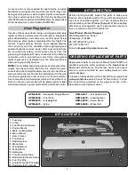
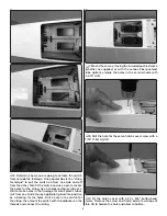
8. Guide the pushrod up through the back of the
fuselage and temporarily connect it to the servo.
❏
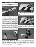
9. With the V-tail and torque rods temporarily held
in place and the ruddervator and elevator servo wheel
centered
, mark the pushrod tube at the ball. This is where
the socket on the ball link must end up after the back of
the pushrod is done. Remove the pushrod.
❏
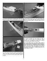
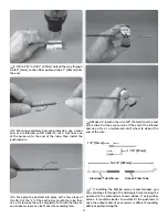
10. Cut the threaded end of the 4" [100mm] pushrod
wire so approximately 1/2" [13mm] of thread remains.
Thread a ball link most of the way onto the threads so
approximately 1/8" [3mm] of the thread is exposed, but
the ball link could be threaded on an additional 1/8" [3mm]
as well—this will leave room for adjustment later. Bend an
“L” bend in the wire 1-1/8" [29mm] from the ball link and
cut off the excess wire.
❏
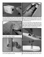
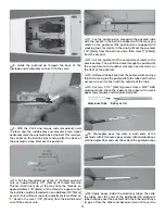
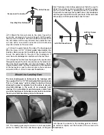
11. Lay the pushrod wire alongside the pushrod tube
with the socket in the ball link aligned with the mark you
made on the pushrod. (The pushrod was wrapped with
masking tape for clarity in the photo.) Mark the pushrod
1/8" [3mm] from the ball link and a third mark 1" [25mm]
from the second.
❏
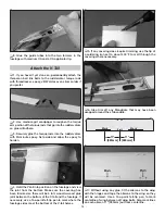
12. Cut the pushrod at the second mark made in the
previous step. Then, drill the holes through the pushrod at
the second mark. Cut another slot same as was done on
the front of the pushrod.
❏
13. Unthread the ball link from the pushrod wire and use
thin CA to tack-glue the pushrod into the tube and trim the
excess wire so it is fl ush with the outside of the tube.
❏
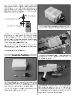
14. Cut two 1-1/2" [40mm] pieces from a 3/16" K&S
aluminum tube. Clean the inside of the tubes with a small
paper towel square and denatured alcohol.
Aluminum Tube
Epoxy or CA
❏
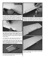
15. Thoroughly pack the slots in both ends of the
pushrods with 30-minute epoxy mixed with microballoons
or milled glass fi ber and coat the ends of the pushrod tubes.
❏
16. Apply epoxy inside the aluminum tubes, then slip
the tubes over the ends of the pushrods (the aluminum
tube that goes over the pushrod with the Z-bend will have
to go on from the other end because it won’t fi t over the


