13
We’re going to instruct you to center the servos and
adjust the pushrods now, but this could be done later
during fi nal setup if you prefer.
❏
3. Temporarily connect the servos to your receiver with a
battery and a switch so you can move the servos with your
transmitter. Turn on your transmitter and make sure the trims
are centered and turn on the receiver.
90˚
90˚
NO
NO
YES
CUT OFF THE
UNUSED ARMS
GREAT PLANES
LARGE-SCALE ARM
❏
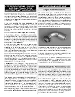
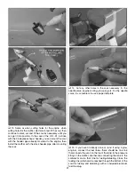
4. Mount your servo arms to the servos—if using the
recommended Great Planes large-scale servo arms,
position the square plastic inserts so the servo arms will be
90-degrees to the servo. If using the standard servo arms that
came with your servos, fi nd the arm that will be 90-degrees
to the servo and cut off the remaining unused arms.
❏
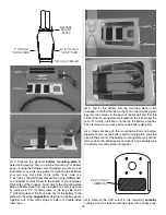
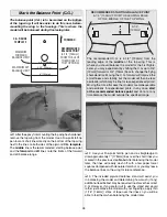
5. Read the following
Expert Tip
about how to solder
pushrods, then make the pushrods and connect the rudder
and elevator with the pushrods and control horns as shown
in the photos.
IMPORTANT:
Be certain you are soldering the
solder clevises
onto the non-threaded end of the pushrods
and threading the
threaded clevises
onto the threaded end
of the pushrods. Sometimes modelers mistake unthreaded
clevises for threaded clevises.
Note:
Make sure the horns
are-mounted over the hardwood plates built into each control
surface and are positioned as thown in the sketch at step 6.
And drill 1/16" [1.6mm] holes for the #2 x 1/2" [12.7mm] Phillips
horn mounting screws. Don’t forget the important procedure
of installing, then removing the screws and hardening the
holes with thin CA.
HOW TO SOLDER
❏
A. Use denatured alcohol or other solvent to thoroughly
clean the pushrod. Roughen the end of the pushrod with
coarse sandpaper where it is to be soldered.
❏
B. Apply a few drops of soldering fl ux to the end of
the pushrod, then use a soldering iron or a torch to heat
it. “Tin” the heated area with
silver solder
(Stay Brite,
STAR2000) by applying the solder to the end. The heat of
the pushrod should melt the solder—not the fl ame of the
torch or soldering iron—thus allowing the solder to fl ow.
The end of the wire should be coated with solder all the
way around.
❏
C. Place the clevis on the end of the pushrod. Add
another drop of fl ux, then heat and add solder. The same
as before, the heat of the parts being soldered should
melt the solder, thus allowing it to fl ow. Allow the joint to
cool naturally without disturbing. Avoid excess blobs, but
make certain the joint is thoroughly soldered. The solder
should be shiny, not rough. If necessary, reheat the joint
and allow to cool.
❏
D. Immediately after the solder has solidifi ed, but while
it is still hot, use a cloth to quickly wipe off the fl ux before
it hardens.
Important:
After the joint cools, coat with oil
to prevent rust.
Note:
Do not use the acid fl ux that comes
with silver solder for electrical soldering.
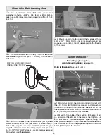
This is what a properly soldered clevis looks like—shiny
solder with good fl ow, no blobs, fl ux removed.
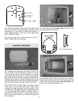
“JAM” NUT
SILICONE RETAINER
❏
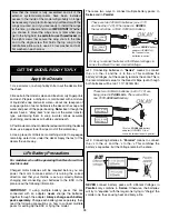
6. After all the pushrods have been made and the elevator
and rudder connected, tighten the 4-40 “jam” nuts to
the threaded clevises and install silicone retainers on all
the clevises.
Summary of Contents for Reactor ARF
Page 36: ......


