background image

32

PREFLIGHT

Identify Your  Model

No matter if you fl y at an AMA sanctioned R/C club site or if 
you fl y somewhere on your own, you should always have your 
name, address, telephone number and AMA number on or 
inside your model. It is 

required

 at all AMA R/C club fl ying sites 

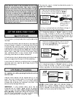
and AMA sanctioned fl ying events. Fill out the identifi cation tag 
on the decal sheet and place it on or inside your model.

Charge the Batteries

Follow the battery charging instructions that came with your 
radio control system to charge the batteries. You should 
always charge your transmitter and receiver batteries the night 
before you go fl ying, and at other times as recommended by 
the radio manufacturer.

CAUTION:

 Unless the instructions that came with your 

radio system state differently, the 

initial 

charge on 

new 

transmitter and receiver batteries should be done for 15 
hours 

using the slow-charger that came with the radio 

system

. This will “condition” the batteries so that the 

next charge may be done using the fast-charger of your 
choice. If the initial charge is done with a fast-charger the 
batteries may not reach their full capacity and you may be 
fl ying with batteries that are only partially charged.

Balance Propellers

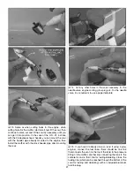
Carefully balance your propeller and spare propellers before 
you fl y. An unbalanced prop can be the single most signifi cant 
cause of vibration that can damage your model. Not only 
will engine mounting screws and bolts loosen, possibly with 
disastrous effect, but vibration may also damage your radio 
receiver and battery. Vibration can also cause your fuel to 
foam, which will, in turn, cause your engine to run hot or quit. 

We use a Top Flite Precision Magnetic Prop Balancer 
(TOPQ5700) in the workshop and keep a Great Planes 
Fingertip Prop Balancer (GPMQ5000) in our fl ight box.

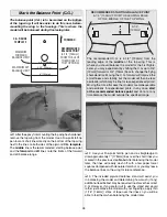
 3. If the tail drops, the model is “tail heavy.” The battery 

pack and/or receiver could be moved forward to get the model 
to balance, or weight could be added to the nose. If the nose 
drops, the model is “nose heavy” and the battery pack and/or 
receiver could be moved aft, or weight could be added to the 
tail. If relocating the receiver and/or battery is not practical, or 
if additional weight is still required after doing so, nose weight 
may be easily added by using “spinner weight” (GPMQ4645 
for the 1 oz. [28g] weight, or GPMQ4646 for the 2 oz. [57g] 
weight). If spinner weight is not practical or is not enough, 
or if tail weight is required, use Great Planes “stick-on” lead 
(GPMQ4485). To fi nd out how much weight is required, place 
incrementally increasing amounts of weight on the fuselage 
over the location where it would be mounted inside until the 
plane balances. A good place to add stick-on nose weight 
is to the fi rewall. 

Do not

 attach weight to the cowl—this will 

cause the mounting screws to open up the holes. Once you 
have determined the amount of weight required, it can be 
permanently attached. If required, tail weight may be added 
by cutting open the bottom of the fuselage and gluing it 
permanently inside. 

Note:

 If mounting weight where it may 

be exposed to fuel or exhaust, do not rely upon the adhesive 
on the back to permanently hold it in place. Over time, fuel 
and exhaust residue may soften the adhesive and cause the 
weight to fall off. Instead, permanently attach the weight with 
glue or screws. 

 4. 

IMPORTANT:

 If you found it necessary to add any weight, 

recheck the C.G. after the weight has been installed.

Balance the Model Laterally

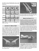
 1. With the wings level, lift the model by the engine propeller 

shaft and the bottom of the fuselage under the trailing edge 
of the fi n. Do this several times.

 2. If one wing always drops when you lift the model, it means 

that side is heavy. Balance the airplane by adding weight 
to the other wing tip.

 An airplane that has been laterally 

balanced will track better in loops and other maneuvers.

Summary of Contents for Reactor ARF

Page 1: ...place of purchase To make a warranty claim send the defective part or item to Hobby Services at the address below Hobby Services 3002 N Apollo Dr Suite 1 Champaign IL 61822 USA Include a letter stati...

Page 2: ...Thank you for purchasing the Great Planes Reactor 60 biplane The Reactor brings new blood into the hobby by combining the stable predictable flight characteristics of models from the old days with the...

Page 3: ...r provide you with a top quality thoroughly tested kit and instructions but ultimately the quality and flyability of your finished model depends on how you build it therefore we cannot in any way guar...

Page 4: ...ty power and the overall battery life will be diminished 1 Great Planes ElectriFly Equinox LiPo Cell Balancer for each battery to be charged simultaneously is recommended Finally propeller selection h...

Page 5: ...servo extensions for digital servos FUTM4145 OR 3 Hobbico Pro 24 610mm heavy duty servo extensions for digital Futaba servos HCAM2721 These are the order numbers for the elevator and rudder servo exte...

Page 6: ...model airplane covering iron but in an emergency a regular iron could be used A roll of MonoKote includes full instructions for application Following are the colors used on this model and order number...

Page 7: ...to make sure they are of acceptable quality If any parts are missing or are not of acceptable quality or if you need assistance with assembly contact Product Support When reporting defective or missin...

Page 8: ...poxy cleanup and other general cleanup throughout assembly ASSEMBLE THE FUSELAGE Test Mount the Elevator and Rudder Servos It will be easier to cut the covering from the servo mounts and drill the ser...

Page 9: ...ill harden the threads cut by the screws to keep your servos securely mounted Mount the Horizontal Stabilizer Stab 1 Use30 minuteepoxytoglueboth6x25mmbottomwing dowels into the bottom wing with 1 4 6m...

Page 10: ...string until the line on the tape aligns with the tip Swing the string over to the same spot on the other side of the stab If the mark on the tape doesn t align rotate the stab and slide the tape unti...

Page 11: ...s so they go in easier 2 Stick a pin through the middle of three hinges Without glue fit the hinges into the hinge slots in one side of the stab The T pins will keep the hinges centered 3 Join the mat...

Page 12: ...th the hinges Wipe away any excess epoxy 10 Remove the pins from the hinges and permanently join the rudder to the fuselage by gluing in the hinges with thin CA Hook Up the Elevator and Rudder 1 Conne...

Page 13: ...edure of installing then removing the screws and hardening the holes with thin CA HOW TO SOLDER A Use denatured alcohol or other solvent to thoroughly clean the pushrod Roughen the end of the pushrod...

Page 14: ...cker 4 Mount the main landing gear to the fuselage with six 4 40 x 3 4 19mm SHCS and 4 lock washers and flat washers use a drop or two of threadlocker on the threads of the screws Mount the Motor If m...

Page 15: ...the plate with the strap Suggestion Hold the two battery packs together with a few small strips of Velcro or double sided foam tape 4 Test fit the battery and the mounting plate in the fuselage note...

Page 16: ...e wires and make certain they will not rub on the motor or motor shaft Mount the Engine A 4 stroke is shown in the photos but the procedure for a 2 stroke is the same 1 Temporarily mount the included...

Page 17: ...line will be the pickup line that goes to the carburetor The bent tube will be connected to the vent pressure line that will go to the pressure tap on the muffler 2 Write BOTTOM on either of the two n...

Page 18: ...he retaining lip in the fuselage for the hatch have been fuelproofed but if you would like to completely seal off the area cut the hatch seal template from page 35 and use spray adhesive to mount it t...

Page 19: ...d mark where the cut needs to be enlarged In the photo the cowl isn t very close to fitting but it s a start 4 Continue to fit mark and cut the cowl as necessary until you can get it at least partiall...

Page 20: ...32 2 4mm holes through the cowl at each mark 10 Remove the cardstock templates Reposition the cowl and spinner Holding the cowl in position use the holes in the cowl as a guide for drilling four 3 32...

Page 21: ...r mounting the cowl 14 Cut any other holes in the cowl necessary for the needle valve engine cooling glow plug etc For the needle valve it is convenient to use a paper template 15 If you haven t alrea...

Page 22: ...ounting blocks on the end of the servo that has the wire coming out of it Drill 1 16 1 6mm holes into the blocks for the mounting screws 3 Mount the servo to the blocks with the screws that came with...

Page 23: ...2 x 3 8 9 5mm button head screws This will require a 050 ballwrench as mentioned in the front of this manual 8 The same as was done for the elevators and rudder make the pushrods and connect the bott...

Page 24: ...0 x 3 8 9 5mm Phillips screws and 4 flat washers Push the wing struts all the way down to the wing to make sure the tabs are set correctly Allow the epoxy to harden WING BOLT PLATE REMOVE THE COVERING...

Page 25: ...is hardening Use care not to inadvertently glue the wing brace to the dowels or the wing 11 Temporarily fasten the remaining four wing strut tabs to the top of both wing struts Without using any glue...

Page 26: ...e balance lines on the wing for future reference 3 The included plywood balance stand will assist you in balancing the model and determining how much if any additional lead ballast may be required to...

Page 27: ...ting holes where preferred 3 Connect the rudder and elevator servo wires to the receiver Connect a dual servo connector to the aileron channel in the receiver then connect a 12 305mm servo extension t...

Page 28: ...IMPORTANT Whether you choose to mount the wings now or later when you get to the flying field be certain to use threadlocker on the eight screws that secure the wing struts to the tabs and to the sin...

Page 29: ...ow the same way NO Also NEVER connect battery packs with different capacities in Series or in Parallel Check the Control Directions 1 If you have not yet done so mount the wings and connect the ailero...

Page 30: ...tuation gives the greatest mechanical advantage of the servo over the control surface which will increase the servo s centering capabilities and output torque minimize any free play in the system and...

Page 31: ...d causing a false reading If not using the balance stand lift the model with your fingers on the middle line 4 Measure and set the low rate elevator throws and the high and low rate throws for the res...

Page 32: ...e model is tail heavy The battery pack and or receiver could be moved forward to get the model to balance or weight could be added to the nose If the nose drops the model is nose heavy and the battery...

Page 33: ...quency sharing agreement listed in the complete AMA Safety Code 9 Under no circumstances may a pilot or other person touch a powered model in flight nor should any part of the model other than the lan...

Page 34: ...dder to keep the model pointing down the runway Allow the model to break ground and establish a gentle climb Be ready on the controls to get the model tracking straight Then make your first turn away...

Page 35: ...ause of poor planning and impulsive moves Remember to think Have a ball But always stay in control and fly in a safe manner GOOD LUCK AND GREAT FLYING Flight If you re a less experienced modeler your...

Page 36: ......

Reviews: