8
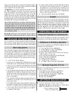
has cooled slide the clevis retainer over the solder clevis.
Center you servo and then install the pushrod into the control
horn and the servo arm. Adjust the clevis as needed and then
tighten the 4-40 nut against the clevis. Be sure to apply a drop
of thread locker to the threaded wire and nut.
❏ ❏
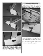
14. Locate two anti-rotation pins. Apply epoxy to the
ribbed end of the pin and into the two holes at each end of
the root rib. Insert the pin into the hole leaving approximately
3/8" [9.5mm] of the pin extending from the root rib. Clean
any excess epoxy with denatured alcohol and a paper towel
before the glue hardens. Set the wing aside to allow the glue
to harden.
❏
15. Repeat steps 1-14 for the left wing panel.
BUILD THE FUSELAGE
Assemble the Tail Section
❏
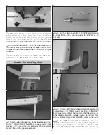
1. Locate the 9-1/2" [241mm] and 19-3/4" [501mm] carbon
fi ber stab tubes. Insert them into the fuselage as shown.
❏
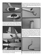
2. Locate the left and right halves of the stab/elevator, two
aluminum ribs and four 4-40 x1/2" [13mm] machine screws.
Install the aluminum ribs to each of the stabs with two 4-40
screws. Be sure that you use thread locker on each of the
screws. During the assembly be sure the side of the rib with
the counter sink faces the outside of the rib. This allows the
screw to be fl ush with the surface of the rib.
Summary of Contents for Revolver 50cc
Page 32: ...GPMA1425 Mnl...


