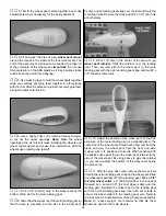
❏
1. Our plane flew great using the Great Planes GD-600
geardrive (GPMG0850). If you would prefer to use a 600
size motor on direct drive, drill the mounting holes in the
motor front plate to match the mounting screw size for your
motor. Most motors require an 1/8" [3.2mm] hole. Slide the
die-cut 3-ply optional motor mount plate through the side
of the motor mount. Insert the second 3-ply motor support in
the optional motor mount plate. Mount the motor to the front
plate with the mounting screws sized for your motor.
❏
2. If you are using the recommended Great Planes GD-
600 geardrive system (GPMG0775) with a S-60014R motor
and C-30 electronic speed control, attach the geardrive to
the front of the motor and solder the capacitors and wires,
from the ESC, to the back of the motor, as shown in the ESC
instructions. Use a 7/64" [2.7mm] drill bit to drill mounting
holes at the punch marks in the front plate. Install the
motor/geardrive in the motor mount using two #4 x 3/8"
[9.5mm] sheet metal screws. Wrap two #64 rubber bands
around the motor and motor mount.
❏
3. Use Velcro Hook and Loop material to mount the
speed control on the side of the fuselage. The material will
adhere better if you first apply thin CA to the balsa sheeting
and allow it to cure before applying it. Plug the ESC, rudder
and elevator servos into the receiver. After the C.G. location
is checked and the motor battery location is determined, the
receiver can be attached to the fuselage side similar to the
ESC. On our show model, we waited until after the model
was covered to install the on/off switch from the ESC. We
installed it in the center of the black stripe on the side of the
fuselage.
❏
4. Connect the 8.4 volt motor battery into the ESC. Switch
on the transmitter, then the ESC, and center the trims on
your transmitter and the servo arms on the rudder and
elevator servos.
❏
5. With the servos centered and the control surfaces in
neutral position, use a felt-tip pen to mark where the
elevator and rudder pushrods cross the mounting holes in
the servo arms. Note: The servo arms have been painted
for clarity.
Install the Motor & Speed Control
33
Summary of Contents for Ryan STA EP
Page 7: ...7 DIE CUT PATTERNS...
Page 48: ...TWO VIEW DRAWING Use copies of this page to plan your trim scheme...
Page 49: ...B C...
Page 50: ...D A...


