❏ ❏
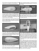
7. Connect the aileron servo to the receiver with a
Y-connector. Center the servo arm and set the aileron to
neutral. Mark where the pushrod crosses the servo arm.
Make a 90° bend at the mark, cut the pushrod and attach it
to the servo arm with a Faslink.
❏
8. Return to step one of
“Install the Aileron Pushrods”
and install the other aileron servo.
❏ ❏
1. Insert the 1/8" [3.2mm] main landing gear in the
slot of the landing gear rail.
❏ ❏
2. Position the two nylon landing gear straps over the
main landing gear as shown on the plan. Mark the screw
hole locations on the landing gear rail.
❏ ❏
3. Drill a 1/16" [1.6mm] diameter pilot hole at each mark.
❏ ❏
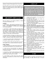
4. Temporarily secure the main landing gear to the
landing gear rail with the landing gear straps and four #2 x
3/8" sheet metal screws.
❏
5. Return to step 1 of
“Mount the Landing Gear” and
install the main landing gear in the other wing half.
❏ ❏
1. Trim one matching set of wheel pant halves along
the molded cut lines. You can use a hobby knife to carefully
score along the cut lines and flex the plastic until the excess
breaks free, or use Hobbico Curved-tip Canopy Scissors
(HCAR0667) to cut along the lines. Notice that the top of the
inner pant goes over the lip of the outer pant. For now, don’t
worry about accurately cutting out the opening in each wheel
pant half – just cut an approximate opening for the wheels.
❏ ❏
2. Use a sanding bar to carefully true the edges of the
overlapping pieces of the wheel pant halves so when they
are glued together the seam will be as small and straight as
possible. Use 320-grit sandpaper to roughen the inside of
both pants and the outside along the gluing tab.
Assemble the Wheel Pants
Mount the Landing Gear
FINISH THE FUSELAGE ASSEMBLY
35
Summary of Contents for Ryan STA EP
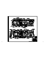
Page 7: ...7 DIE CUT PATTERNS...
Page 48: ...TWO VIEW DRAWING Use copies of this page to plan your trim scheme...
Page 49: ...B C...
Page 50: ...D A...


