❏ ❏
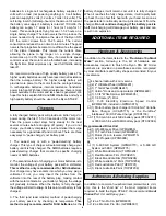
2. From the 3/16" x 3/8" x 24" [4.8mm x 9.5mm x 609.6mm]
balsa stick, cut and glue the remainder of the frame and the
LE doubler.
❏ ❏
3. From the 3/16" x 3/16" x 30" [4.8mm x 4.8mm x 762mm]
balsa stick, cut and glue the elevator ribs to the elevator frame.
❏
4. Repeat step 1 through step 3 to build the second
elevator half.
❏
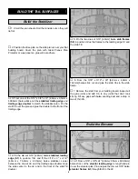
5. Remove the elevators from your building board. Inspect
all the glue joints and add CA to any joints that don’t look
strong. Sand the stabilizer and elevators to shape using the
fuse plan as a guide. Sand both sides of the stabilizer and
elevator flat and even. Be careful that you don’t sand any
area too thin. Do not bevel the LE of the elevator until after
the hinges have been installed.
❏
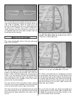
6. Pin both elevator halves in position over the plan. Lay
the 3/32" elevator joiner wire on top of the elevators in the
position shown on the plan. Use a pencil to lightly mark the
outline of the joiner wire on the elevators.
❏
7. Using a straightedge, extend the sidelines of the
elevator joiner outline forward to the leading edge. Also, use
a Great Planes Precision Hinge Marking Tool
™
(GPMR4005)
to draw a centerline on the leading edge of both elevator
halves. Using these lines, you can determine exactly where
to drill the holes for the elevator joiner wire.
❏
8. Drill a 3/32" hole through the leading edge of both
elevators. As you drill each hole, keep the drill aligned with
the top and bottom surface of the elevator and reference
lines you made in the previous steps.
❏
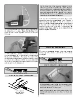
9. Refer to the
Expert Tip that follows to cut a 3/32"
groove in the leading edge of both elevators to recess the
joiner wire.
B. Use the sharpened tube to
carefully gouge the leading
edge of the elevators. You’ll have to make several passes
to make the recess deep enough for the joiner wire.
A. Use a #11 knife blade to sharpen the inside of a piece
of 3/32" brass tube. Roll the tube as you sharpen the end.
HOW TO CUT A GROOVE FOR A JOINER WIRE
9
Summary of Contents for Ryan STA EP
Page 7: ...7 DIE CUT PATTERNS...
Page 48: ...TWO VIEW DRAWING Use copies of this page to plan your trim scheme...
Page 49: ...B C...
Page 50: ...D A...


