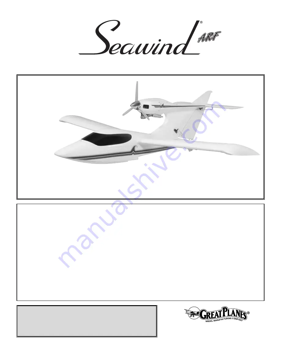
background image

WARRANTY

Great Planes

®

Model Manufacturing Co. guarantees this kit to be free from defects in both material and workmanship at the date of purchase. This

warranty does not cover any component parts damaged by use or modification. In no case shall Great Planes' liability exceed the original cost of
the purchased kit. 
Further, Great Planes reserves the right to change or modify this warranty without notice.

In that Great Planes has no control over the final assembly or material used for final assembly, no liability shall be assumed nor accepted for any
damage resulting from the use by the user of the final user-assembled product. By the act of using the user-assembled product, the user accepts all
resulting liability.

If the buyer is not prepared to accept the liability associated with the use of this product, the buyer is advised to return this kit immediately
in new and unused condition to the place of purchase.

To make a warranty claim send the defective part or item to Hobby Services at the address below:

Hobby Services

3002 N. Apollo Dr., Suite 1

Champaign, IL 61822

USA

Include a letter stating your name, return shipping address, as much contact information as possible (daytime telephone number, fax number, e-mail
address), a detailed description of the problem and a photocopy of the purchase receipt. Upon receipt of the package the problem will be evaluated as
quickly as possible.

READ THROUGH THIS  MANUAL  BEFORE  STARTING
CONSTRUCTION.

IT CONTAINS IMPORTANT

INSTRUCTIONS AND WARNINGS CONCERNING
THE ASSEMBLY AND USE OF THIS MODEL.

GPMZ0242 for GPMA1360  V1.0

Entire Contents © Copyright 2005

Champaign, IL

(217) 398-8970, Ext. 5

airsupport@greatplanes.com

INSTRUCTION MANUAL

Wingspan: 71 in [1805mm] 
Wing Area: 676 sq in [43.6 dm

2

Weight: 10.25 – 12.25 lb [4620 – 5555g]
Wing Loading: 35 – 41 oz/sq ft [106 – 127 g/dm

2

Length: 56 in [1410mm] 
Radio: 5 or 6-channel with 7-9 servos
Engine: .60 cu in [10cc] two-stroke,

.70 – .91 cu in [11.5 – 15cc] four-stroke

Summary of Contents for Seawind ARF

Page 1: ...ly in new and unused condition to the place of purchase To make a warranty claim send the defective part or item to Hobby Services at the address below Hobby Services 3002 N Apollo Dr Suite 1 Champaig...

Page 2: ...ing plane and developed a 60 size ARF Now you too can fly from land or water opening up new flying sites not available before Many hours of development and test flying have gone into the Great Planes...

Page 3: ...not a member of a club your local hobby shop has information about clubs in your area whose membership includes experienced pilots 8 While this kit has been flight tested to exceed normal use if the p...

Page 4: ...iron TOPR2100 Top Flite Hot Sock iron cover TOPR2175 Top Flite MonoKote trim seal iron TOPR2200 Top Flite MonoKote heat gun TOPR2000 21st Century sealing iron COVR2700 21st Century iron cover COVR270...

Page 5: ...y shop is not available replacement parts may also be ordered from Tower Hobbies at www towerhobbies com or by calling toll free 800 637 6050 Parts may also be ordered directly from Hobby Services by...

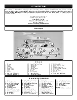
Page 6: ...ip 6 Large Control Horn 34 2 x 3 8 9 5mm Philips Screws 7 2 56 x 6 152mm Pushrod Threaded One End 8 Nylon FasLink 8 1 4 6 4mm Silicone Clevis Retainer 2 Screw Lock Pushrod Connector 2 4 40 x 1 4 Socke...

Page 7: ...reat Planes Dead Center hole locator to mark on the engine mount the four engine mounting holes 5 Remove the engine mount and use a drill press if you have one to drill a 9 64 3 5mm hole at each mark...

Page 8: ...nk when inserted Do not kink the tube Mark a P on the outside of the front plate to designate pressure 3 Install a piece of fuel tubing on each of the other two tubes Attach a clunk on the ends of the...

Page 9: ...tray block 5 Connect a 36 914mm servo extension to the throttle servo Tie the string in the fuel tank compartment to the end of the extension and pull the extension through the tube and into the fusel...

Page 10: ...9 5mm self tapping screws and 2 flat washers 6 Remove the spinner backplate and the cowl Using the template method locate and cut the hole for the needle valve Connect the fuel line to the carburetor...

Page 11: ...with epoxy thinned with denatured alcohol to prevent the wood from soaking up water 4 Use sandpaper to roughen the inside of the nose gear opening where the cover plate will be glued Clean the area wi...

Page 12: ...the steering servo using the hardware that came with your radio 6 Drill a 3 32 2 4mm hole through the aft edge of the nose wheel recess 1 25 4mm from the bottom of the fuselage You will need to remov...

Page 13: ...Position the landing gear block in the metal main landing gear mount so that the landing gear wire goes through the mount Drill a 7 64 2 7mm pilot hole at each mounting hole location and attach the l...

Page 14: ...lve Attach air line tubing between the air tank and fill valve 5 Attach the control valve to the plywood control valve mount Attach the air line tubing to the control valve and glue the mount to the r...

Page 15: ...cable in one of the holes The masking tape will prevent the cable from pulling through the hole Slide a metal furl on the cable inside the fuselage Then thread the cable through the bottom hole in the...

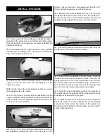
Page 16: ...in the center of the hinge Insert the hinges in the stabilizer and install the elevator Remove the T pins and adjust the control surface so that the leading edge of the elevator is against the trailin...

Page 17: ...to the string and carefully pull the extension through the fuselage Tape or heat shrink the leads together 2 Install the elevator servo in the fuselage using the hardware supplied with the servo 3 Thr...

Page 18: ...e sure the control horn is installed over the hardwood block 11 Install the flap pushrod on the flap servo arm following the same procedure used to install the aileron pushrod Note If you will be usin...

Page 19: ...tips are well sealed to the wing to prevent any water from getting in You may want to apply clear tape or silicone sealant around the edges of the wing tips to seal them 1 Insert the aluminum wing joi...

Page 20: ...n easily be glued to the side of the fuselage with CA For best adhesion roughen the area with sandpaper before applying CA 1 Glue the rubber bushing in the end of the aluminum bailing tube opposite th...

Page 21: ...s indicated in the chart that follows If your radio does not have dual rates we recommend setting the throws at a rate in between the high and low rates Note The throws are measured at the widest part...

Page 22: ...the model it means that side is heavy Balance the airplane by adding weight to the other wing tip An airplane that has been laterally balanced will track better in loops and other maneuvers No matter...

Page 23: ...from high heat sparks or flames as fuel is very flammable Do not smoke near the engine or fuel and remember that engine exhaust gives off a great deal of deadly carbon monoxide Therefore do not run t...

Page 24: ...f you will be flying off of water check all the joints where water may enter and seal them with clear tape or silicone sealant 2 Check the C G according to the measurements provided in the manual 3 Be...

Page 25: ...e ailerons to keep the wings level and be smooth on the elevator stick allowing the model to establish a gentle climb to a safe altitude before making the first turn away from yourself Do not yank bac...

Page 26: ...you re ready to make your landing flare and the model is a foot or so off the deck smoothly increase up elevator until it gently touches down One final note about flying your model Have a goal or fli...

Page 27: ...s most at home rocketing around pylons at breathtaking speeds GPMA1320 Great Planes Lancair ES 60 ARF The original Lancairs were high performance homebuilts Great Planes version is high performance to...

Page 28: ...____________ Where Purchased _________________________ Date Construction Started __________________ Date Construction Finished _________________ Finished Weight __________________________ Date of Firs...

Reviews: