20
❏
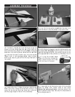
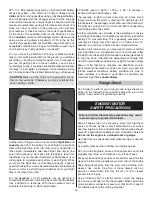
10. Medium CA will be used to glue the cowl to the cowl
ring, but you’ll need an extended glue tip in order to reach
down inside. Pipettes and Tefl on tubing may be used, but we
used a length of micro pushrod tubing fi t over a CA tip.
❏
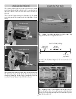
11. Double-check that the cowl is positioned
precisely
as
you want it viewing it from all angles to make sure. The rubber
band should securely hold the cowl in position while gluing.
❏
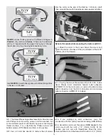
12. Use your extended glue tip to tack-glue the cowl to the
ring with medium CA wherever you can reach—for now, the
cowl only needs to be tack-glued well enough to hold during
removal.
❏
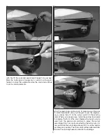
13. Once you’ve got the cowl glued to the cowl ring, use
your extended hex driver to remove the cowl screws. Then,
take off the cowl.
❏
14. Securely glue the back of the cowl ring with thin CA
and the front of the cowl ring with medium CA.
❏
15. If running a glow engine and the bottom cowl ring
screws are not accessible through the air inlet in the front of
the cowl, cut a rounded slot on both sides of the cowl for the
hex driver. If the bottom two screws are accessible through
the inlet, the slots may not be necessary.
Proceed to “Finish the Cowl” on page 22.
Summary of Contents for Sequence 1.20
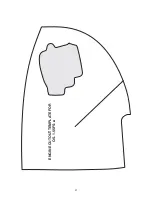
Page 31: ...31 ENGINE CUTOUT TEMPLATE FOR O S 1 55FS a...
Page 32: ......

