6
ASSEMBLE THE WINGS
❏
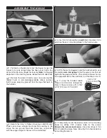
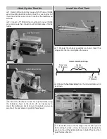
1. Pull hard on the ailerons to test the hinges. Inspect the
hinges to be sure enough glue has been used. Add a few
drops of thin CA to any hinges that look dry.
Note:
CA “fogging”
deposited on the covering can be cleaned with CA debonder.
❏
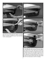
2. Remove the aileron hatch covers and use naphtha
(lighter fl
uid) or commercially-available sticker removal
fl uid to wipe away any glue left from the tape that held on
the hatches.
❏
3. Refer to the “How to Tighten Covering on ARF Models”
sheet and remove wrinkles and bond the covering to the
wings. You can go over the whole model now, or just start
with the wings and get to the rest of the model later.
❏
4. Use thin CA followed by a
small
fi llet of medium CA to
reinforce the servo mounting blocks to the hatch covers.
❏
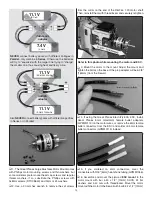
5. With the servos plugged in and the radio turned on, use
the plastic
servo arm gauge
to fi nd the servo arms that will
align with the gauge as shown. (This will allow the servo arms
to be perpendicular to the pushrods.) Cut the other arms off.
❏
6. If using the included Great
Planes 4-40 ball links, enlarge the
holes in the servo arms with a 7/64"
or 1/8" [2.8mm or 3.2mm] drill.
❏
7. Temporarily mount the aileron servos to the mounting
blocks by drilling 1/16" [1.6mm] holes for the screws.
Remove the screws and servos.
Use a few drops of thin
CA to harden the screw holes. Allow the CA to harden before
remounting the servos.
7/64" or 1/8"
[2.8mm–3.2mm]
Summary of Contents for Sequence 1.20
Page 31: ...31 ENGINE CUTOUT TEMPLATE FOR O S 1 55FS a...
Page 32: ......

