background image

WA

MF

GR

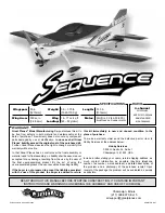
Motor:

RimFire .32 (42-50-800)

brushless out-runner motor

Length:

51.5 in
[1310mm]

w/4 micro servos

and standard

size receiver

4-channel

minimum

Wingspan:

50 in
[1270mm]

Wing Area:

505 sq in
[32.6 dm

2

Weight:

3.5– 3.75 lb
[1590-1700 g]

Wing

Loading:

16– 17 oz/sq ft
[49– 52 g/dm

2

]

SPECIFICATIONS

RADIO

Champaign, Illinois

(217) 398-8970, Ext 5

airsupport@greatplanes.com

Entire Contents © Copyright 2009

GPMA1575 Mnl

READ THROUGH THIS MANUAL BEFORE STARTING CONSTRUCTION. IT CONTAINS IMPORTANT

INSTRUCTIONS AND WARNINGS CONCERNING THE ASSEMBLY AND USE OF THIS MODEL.

WARRANTY

Great Planes

®

 Model Manufacturing Co. guarantees this kit to 

be free from defects in both material and workmanship at the 
date of purchase. This warranty does not cover any component 
parts damaged by use or modification. In no case shall Great 
Planes’ liability exceed the original cost of the purchased kit.
 
Further, Great Planes reserves the right to change or modify this 
warranty without notice.

In that Great Planes has no control over the final assembly or 
material used for final assembly, no liability shall be assumed nor 
accepted for any damage resulting from the use by the user of 
the final user-assembled product. By the act of using the 
user-assembled product, the user accepts all resulting liability.

If the buyer is not prepared to accept the liability associated 
with the use of this product, the buyer is advised to return 

this kit immediately in new and unused condition to the 
place of purchase.

To make a warranty claim send the defective part or item to 
Hobby Services at the address below:

Hobby Services

3002 N. Apollo Dr.  Suite 1

Champaign IL  61822  USA

Include a letter stating your name, return shipping address, as 
much contact information as possible (daytime telephone 
number, fax number, e-mail address), a detailed description of 
the problem and a photocopy of the purchase receipt. Upon 
receipt of the package the problem will be evaluated as quickly 
as possible.

Summary of Contents for Sequence

Page 1: ...her Great Planes reserves the right to change or modify this warranty without notice In that Great Planes has no control over the final assembly or material used for final assembly no liability shall...

Page 2: ...he build is the pre trimmed cowl and pre installed cowl ring Just snap the cowl in place over the firewall and you re ready to move on Radio equipment and the battery pack are easily accessible beneat...

Page 3: ...s of which may cause eye skin and respiratory tract irritation Never blow into a part to remove fiberglass dust as the dust will blow back into your eyes Always wear safety goggles a particle mask and...

Page 4: ...1x36 DTXR1215 Adhesives and Building Supplies This is the list of Adhesives and Building Supplies that are required to finish the Sequence ARF 1 2 oz 15g Thin Pro CA GPMR6001 Pro 30 minute epoxy GPMR...

Page 5: ...y the foot If only a small piece of MonoKote is needed for a minor patch perhaps a fellow modeler would give you some MonoKote is applied with a model airplane covering iron but in an emergency a regu...

Page 6: ...ve Suite 1 Champaign IL 61822 Be certain to specify the order number exactly as listed in the Replacement Parts List Payment by credit card or personal check only no C O D If additional assistance is...

Page 7: ...s using tape heat shrink tubing not included or special clips designed for that purpose 2 Locate the strings taped inside the aileron servo bays and tie the ends of the strings to the servo extensions...

Page 8: ...nnect the clevises to the outer holes of two control horns Hinge Line Hinge Line CORRECT INCORRECT Hin 6 Position the control horns over the hardwood blocks in the ailerons if you cannot see them hold...

Page 9: ...nsert the carbon wing joiner into the outer wing tube in the fuselage and center it left and right Slide the wing panels onto the tube and tighten them down using the included wing bolts 2 Temporarily...

Page 10: ...ow be removed from the fuselage and set aside Drill a 3 32 2 4mm hole 1 2 13mm deep in the center of the hinge slot Cut the covering away from the slot 4 Drill a 3 32 2 4mm hole 1 2 13mm deep into the...

Page 11: ...ot to get glue into the hole in the bushing 2 Slide the tail gear bracket tail gear collar and nylon post onto the tail gear assembly as shown If necessary enlarge the hole in the nylon post for the t...

Page 12: ...flat spots on the axles Be sure that the wheel rotates freely on the axle Oil the axles if necessary 10 Attach the wheel pants to the landing gear legs using four 2 56 x 3 8 9 5mm machine screws four...

Page 13: ...r to the servo case as shown with the arm pointing toward the center of the fuselage Be sure to reinstall the servo arm screw into the servo use thread locking compound if the servo has a metal output...

Page 14: ...udder pull pull cable exit slots on each side of the fuselage The slots may be difficult to find underneath the covering Measure down 1 3 16 30mm from the underside of the stab in the location shown f...

Page 15: ...evis 4 to 5 complete turns only onto each coupler and a silicone clevis retainer on each clevis Slide a swage onto each aft end of the pull pull strings Feed the string ends through the holes in the c...

Page 16: ...lon clevis silicone clevis retainer control horn FasLink pushrod connector and two 2 x 1 2 13mm self tapping screws 3 Install the elevator servo and pushrod in the same manner Note that the elevator s...

Page 17: ...pplied to the underside of your battery pack 5 Make a strap from the included non adhesive hook and loop material by overlapping the mating ends by approximately 1 25mm The strap is used to hold the b...

Page 18: ...ou have installed the recommended motor you will need to drill or ream the propeller and spinner backplate to 5 16 7 9mm Install the spinner backplate onto the prop adapter followed by the prop prop w...

Page 19: ...2 Connecting batteries in Parallel means to connect the s to the s and the s to the s This combines the batteries capacities but the Voltage remains the same NO NEVER connect battery packs with diffe...

Page 20: ...eft 1 25mm 12 deg Right 1 25mm 12 deg Left AILERONS 3 4 19mm 15 deg Up 3 4 19mm 15 deg Down 1 2 13mm 11 deg Up 1 2 13mm 11 deg Down IMPORTANT The Sequence ARF has been extensively flown and tested to...

Page 21: ...d gluing it permanently inside Note Do not rely upon the adhesive on the back of the lead weight to permanently hold it in place Over time the adhesive may fail and cause the weight to fall off Use 2...

Page 22: ...tion sheet included with your battery Failure to follow all instructions could cause permanent damage to the battery and its surroundings and cause bodily harm ONLY use a Li Po approved charger NEVER...

Page 23: ...the servos with the screws included with your radio 11 Secure connections between servo wires and Y connectors or servo extensions with vinyl tape heat shrink tubing or special clips suitable for that...

Page 24: ...harge but use this first flight to become familiar with your model before landing Landing To initiate a landing approach lower the throttle while on the downwind leg Allow the nose of the model to pit...

Reviews: