15
❏
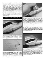
11. Attach the clevises to the outer holes in the rudder
servo arm. Feed the pull-pull strings through the pull-pull
tubes and out the exit slots.
❏
12. Drill a 5/64" [2mm] diameter hole 1-7/8" [48mm]
from the bottom of the rudder and 3/8" [9.5mm] aft of the
rudder hinge line as shown. Be sure that you drill the hole
perpendicular through the rudder. To ensure accuracy, you
may want to mark the location of the hole on each side of the
rudder and partly drill through the rudder from each side, then
connect the two holes by drilling through the entire thickness
of the rudder. Apply a few drops of thin CA to the hole to
harden the surrounding wood. When the CA has hardened,
insert the 2" [51mm] threaded control rod through the hole
and center its position. Tighten a 2mm fl at washer and 2mm
nut with threadlocking compound on each side of the rod as
shown. Finish the rudder control rod by threading a nylon
control rod horn onto each end of the control rod.
❏
13. Thread a 4-40 nut with thread locking compound onto
each of the remaining threaded couplers. Thread a metal
clevis 4 to 5 complete turns only onto each coupler and
a silicone clevis retainer on each clevis. Slide a swage onto
each aft end of the pull-pull strings. Feed the string ends
through the holes in the coupler and back through the
swages but do not crimp the swages yet. Confi rm that the
rudder servo is centered and the rudder is in the neutral
position. Connect the clevises to the control rod horns. Draw
each pull-pull string tight, slide the swage to the base of the
coupler and crimp it onto the strings. Cut off the excess string.
It is likely that there is still some slack in the pull-pull strings.
For precise rudder control, the strings must be equally tight
on both sides. Disconnect the clevises from the control rod
horns and thread the clevises farther onto the couplers.
Reconnect the clevises to the control rod horns and confi rm
that all the slack is out of the strings. Repeat this process
on the servo side of the strings if necessary. When satisfi ed
that the rudder is in the neutral position when the servo is
centered and the strings are equally taut on both sides, slide
the silicone clevis retainers to the ends of the clevises and
tighten the 4-40 nuts against the bases of the clevises. Test
the operation of the rudder using your radio system.


