9
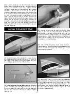
Pushrod Wire
FasLink Pushrod
Connector
Servo Horn
❏
8. Use tape or a small clamp to hold the ailerons in the
neutral position. Make a mark on the pushrods where they
cross the outer holes in the servo arms. Make a 90 degree
bend at the mark on the pushrod and cut off the excess
pushrod 1/4" [6mm] beyond the bend. Attach the pushrods
to the servo arms using FasLink pushrod connectors. Thread
the clevises up or down on the pushrods as necessary to
center the ailerons with the servo arms centered. When
satisfi ed, slide the silicone clevis retainers to the ends of the
clevises to secure them.
❏
9. Use epoxy to glue the nylon wing dowels into the root
rib of each panel. The smooth ends of the dowels should
protrude from the root ribs approximately 1/2" [13mm]. Use a
paper towel dampened with denatured alcohol to wipe away
any excess epoxy.
INSTALL THE HORIZONTAL
STABILIZER AND ELEVATORS
❏
1. Insert the carbon wing joiner into the outer wing
tube in the fuselage and center it left and right. Slide the
wing panels onto the tube and tighten them down using the
included wing bolts.
❏
2. Temporarily install the horizontal stabilizer into the
stab slot. Stand back 5-6 ft [1.5 - 1.8m] and view the model
from behind. Confi rm that the stab and wing are parallel.
If not, sand the slot as necessary until they are parallel. A
weight can also be placed on the high side to bring the stab
parallel with the wing.
Before beginning step 3, have some paper towels, denatured
alcohol, and a tape measure or length of string with some
masking tape on hand and ready to use. When gluing the
stab into the slot, it is recommended to coat both the stab
itself and the slot with epoxy. Doing so will require additional
cleaning of excess epoxy from one side of the stab. However,
a better glue joint is achieved when both mating sides have
epoxy applied to them. We also suggest dry fi tting the stab
with the elevator joiner in place to confi rm that the joiner wire
rotates smoothly and the stab fi ts properly.


