background image

Ground check the operational range of your radio before the
first flight of the day. With the transmitter antenna collapsed and
the receiver and transmitter on, you should be able to walk at
least 100 feet away (consult your radio's instructions for the
exact distance required) from the model and still have control.
If the control surfaces do not respond correctly, 

do not fly!

Find

and correct the problem first. Look for loose servo connections
or broken wires, corroded wires on servo connectors, poor
solder joints in your battery pack or a defective cell, or a
damaged receiver crystal from a previous crash.

Read and abide by the following Academy of Model
Aeronautics Official Safety Code:

1. I will not fly my model aircraft in sanctioned events, air
shows, or model flying demonstrations until it has been
proven to be airworthy by having been previously
successfully flight tested.

2. I will not fly my model aircraft higher than approximately
400 feet within 3 miles of an airport without notifying the
airport operator. I will give right of way to and avoid flying in
the proximity of full scale aircraft. Where necessary an
observer shall be used to supervise flying to avoid having
models fly in the proximity of full scale aircraft.

3. Where established, I will abide by the safety rules for the
flying site I use and I will not willfully and deliberately fly my
models in a careless, reckless and/or dangerous manner.

7. I will not fly my model unless it is identified with my name
and address or AMA number, on or in the model.

9. I will not operate models with pyrotechnics (any device
that explodes, burns, or propels a projectile of any kind).

1. I will have completed a successful radio equipment ground
check before the first flight of a new or repaired model.

2. I will not fly my model aircraft in the presence of
spectators until I become a qualified flier, unless assisted by
an experienced helper.

4. I will operate my model using only radio control frequencies
currently allowed by the Federal Communications Commission.

❏ 

1. Check the C.G. according to the measurements

provided in this manual.

❏ 

2. Be certain the battery and receiver are securely

mounted in the fuse.

❏ 

3. Extend your receiver antenna inside the fuselage.

❏ 

4. Balance your model 

laterally as explained in 

the instructions.

❏ 

5. Make sure all hinges are 

securely

glued in place.

❏ 

6. Reinforce holes for wood screws with thin CA where

appropriate (servo mounting screws, control horns, etc.).

❏ 

7. Confirm that all controls operate in the correct direction

and the throws are set up according to the manual.

❏ 

8. Make sure there are silicone retainers on all the

clevises and that all servo arms are secured to the servos
with the screws included with your radio.

❏ 

9. Secure connections between servo wires and 

Y-connectors or servo extensions and the connection between
your battery pack and the on/off switch with vinyl tape, heat
shrink tubing or special clips suitable for that purpose.

❏ 

10. Make sure all servo extensions you may have used do

not interfere with other systems (servo arms, pushrods, etc.).

❏ 

11. Use an incidence meter to check the wing for twists

and attempt to correct before flying.

❏ 

12. Place your name, address, AMA number and

telephone number on or inside your model.

❏ 

13. Cycle your receiver battery pack (if necessary) and

make sure it is fully charged.

❏ 

14. If you wish to photograph your model, do so before

your first flight.

❏ 

15. Range check your radio when you get to the flying field.

During the last few moments of preparation your mind
may be elsewhere anticipating the excitement of the first
flight. Because of this, you may be more likely to overlook
certain checks and procedures that should be performed
before the model is flown. To help avoid this, a checklist is
provided to make sure these important areas are not
overlooked. Many are covered in the instruction manual,
so where appropriate, refer to the manual for complete
instructions. Be sure to check the items as off they are
completed (that's why it's called a 

check list!).

CHECKLIST

Radio Control

General

AMA SAFETY CODE (

EXCERPT

)

Range Check

19

Summary of Contents for Spirit Elite ARF

Page 1: ...of using the user assembled product the user accepts all resulting liability If the buyer is not prepared to accept the liability associated with the use of this product the buyer is advised to return...

Page 2: ...res flaps and ailerons to provide the ultimate in control when using computer radio mixing functions Take your time and follow the directions carefully to end up with a well built model that is straig...

Page 3: ...HCAM2500 only one required for advanced features 2 12 Servo Extensions HCAM2100 required for advanced features only 1 2 oz Thin Pro CA GPMR6001 1 2 oz Medium Pro CA GPMR6007 30 Minute Epoxy GPMR6047...

Page 4: ...inor patch perhaps a fellow modeler would give you some MonoKote is applied with a model airplane covering iron but in an emergency a regular iron could be used The roll of MonoKote includes full inst...

Page 5: ...2 56 x 3 8 Machine Screws 8 2 56 x 5 8 Machine Screws 4 074 x 4 Threaded One End Pushrods 2 074 x 36 Elev Rudder throttle Pushrods 2 Outer Pushrod Tubes 1 2 x 9 CA Hinge Strip 1 Eyelet 1 4 40 Tow Hoo...

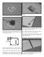
Page 6: ...imes to loosen it up 4 Repeat for the other wing panel 1 Locate the openings for the flap and aileron servos in the bottom of each wing panel Trim out the covering and seal the edges using a sealing i...

Page 7: ...e connection since it will not be easily accessible in the future 9 Tie the string to the extension and pull it through the wing 10 Trim out the servo wire access hole on the bottom of the wing and ro...

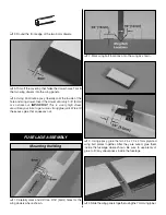
Page 8: ...your time to get a nice strong glue joint Wipe off the excess glue that squeezes out 1 Carefully mark and drill two 3 16 5mm holes for the wing dowels where shown 2 Mark wing bolt locations onto the...

Page 9: ...h a washer to pull them into the wood 8 Trial fit the wing onto the saddle Secure the wing in place using the two 8 32 Cap screws with washers 1 Measure and mark the center of the trailing edge of the...

Page 10: ...readed end of each 074 x 36 wire pushrods This will create two alignment pins for the fin 2 Drill two 1 16 holes 1 5mm into the bottom of the fin where shown Make sure they are centered 3 Glue the ali...

Page 11: ...each hinge not too much or it will run down the hinge line 3 Flip the stab over and glue the other side in the same manner 4 Install two of the CA hinges in the rudder and install onto the fin 5 Glue...

Page 12: ...e tube so it only protrudes 1 8 3mm past the slot 4 Roughen the end of the tube an inch or so 25mm with sandpaper This will provide a better gluing surface 5 Use epoxy to glue the tube to the fuselage...

Page 13: ...Hint To strengthen the holes place one small drop of CA into each hole and redrill 12 Attach the control horn to the elevator and rudder using two 2 56 x 3 8 9mm screws along with the backplate 13 In...

Page 14: ...r forward in the nose as possible 2 Extend the antenna and route through the inside of the fuselage towards the tail Try to keep it as straight as possible 3 Wrap the receiver in 1 4 foam rubber and p...

Page 15: ...l the tow hook into the front hole and tighten This is the preferred location for your initial flights 1 Attach four clevises with retainers onto the 4 short wire pushrods Attach them to the four rema...

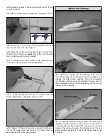
Page 16: ...the mark and insert into the arm Cut off the excess wire leaving only 1 4 6mm after the bend Secure with a Faslink connector 1 Trial fit the canopy onto the fuselage If the canopy does not fit snugly...

Page 17: ...to the fuselage Adjust its position as needed for a good fit 6 Once satisfied with the fit use epoxy to glue the frame to the canopy 7 Attach a small rubber band around the servo tray frame as shown 8...

Page 18: ...s The tow hook should be in the front hole for the first flights After the first flights the tow hook can be moved back to the middle hole for most flying conditions For contest flying you may want to...

Page 19: ...l using only radio control frequencies currently allowed by the Federal Communications Commission 1 Check the C G according to the measurements provided in this manual 2 Be certain the battery and rec...

Page 20: ...as the rubber is long or whatever the hi start instructions recommend Hold the plane above your head with the wings level and the nose pointed slightly up and directly into the wind Give the plane a p...

Page 21: ...hermal days or days with a lot of wind where you might need the reflex capability for zooming up wind The other way we set this switch is to have the back position for neutral camber the middle positi...

Page 22: ...d against any last minute sink or gusts and dump the extra altitude and speed at the last second They can also be used to help control your skid Flaps will stop the plane from sliding a little quicker...

Page 23: ...______________ Where Purchased _________________________ Date Construction Started __________________ Date Construction Finished _________________ Finished Weight __________________________ Date of Fi...

Page 24: ...igh altitude launches Complete system unlimited class sailplanes A Dynaflite Hi Start and 800 of clear launch area are all you need to send your sailplane rocketing up to 500 in the air Easy to lay ou...

Reviews: