background image

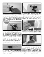
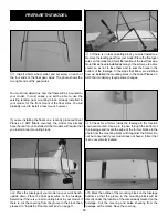
6. This fuselage has a 1/8" [3.2mm] balsa side and a 1/8"

[3.2mm] ply doubler. There is also a 1/4" x 1/4" [6.4 x
6.4mm] balsa filler stick glued to the bottom sheeting and
resting on the edge of the ply doubler. Cut the stick and
fuselage side down to the ply doubler. Do not cut deeper
than 1/2" [12.7mm], the thickness of the mounting block.

7. After cutting down to the ply doubler, the mounting

block will likely protrude from the bottom of the fuselage
slightly; in our case it was 1/8". Trim the fuse side and ply
doubler until the mounting block is flush with the bottom of
the fuselage.

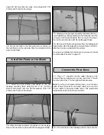
8. Using epoxy, glue the 1/2" x 3/4" x 1" [12.7 x 19 x

25.4mm] support blocks to the fuselage sides as shown in
the photo. If your model does not have a former that the
mounting block can be glued to, you should make longer
support blocks to provide additional support.

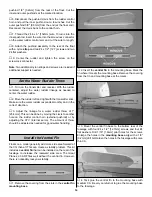
9. Using epoxy, glue the mounting block to the support

blocks, fuselage sides and former. Glue a filler strip to the
mounting block, if needed, so that the bottom sheeting can
be glued to the mounting block.

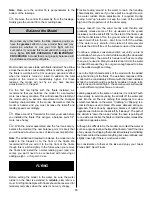
10. Use the covering that you saved to cover the mounting

block and the fuselage sides. There may not be enough
covering, so do the visible part of the fuselage sides first.
Leftover Cub Yellow MonoKote

®

can be used on the bottom.

If the landing gear is still installed on the model, remove it.
Set the parts aside where you won’t misplace them.

1. Install four nylon landing gear straps on each float

using eight #4 x 1/2" [12.7mm] sheet metal screws and
eight #4 flat washers. The side of the straps should be

Install the Float Gear Wires

INSTALL THE  FLOATS

11

Summary of Contents for Sport Float Kit ARF

Page 1: ...ly no liability shall be assumed nor accepted for any damage resulting from the use by the user of the final user assembled product By the act of using the user assembled product the user accepts all...

Page 2: ...not be considered a toy but rather a sophisticated working model that functions very much like a full size airplane Because of its performance capabilities the ARF Sport Floats and model if not assem...

Page 3: ...ded with this kit servo not included We highly recommend that you install a servo inside the float It is easy to do and it makes installation removal of the floats on the aircraft easier Floats increa...

Page 4: ...e 6 Before starting assembly assemble the model and mark the balance point of the model You will need to know this later when the model is balanced with the floats installed Important Building Notes P...

Page 5: ...wn in the above photo 4 Clean any resin residue from the tray opening in the float Trim any resin from the hardwood mounting rail inside the float Put one of the 1 4 x 3 8 x 3 1 2 6 4 x 9 5 x 89mm bas...

Page 6: ...rvo tray as shown and mark the location of the mounting rails 10 Use 6 minute epoxy to glue the basswood blocks to the servo tray with the servo attached The servo should be centered between the lines...

Page 7: ...ro Threadlocker to hold the nut in place Hint Center punch the bracket before drilling the hole 7 Install a screw lock connector nylon retainer and 4 40 x 1 8 3 2mm socket head cap screw in the outer...

Page 8: ...e the hole with a hobby knife 4 Cut the 074 x 17 1 2 445mm wire pushrod to a length of 12 25 4mm Cut the threaded portion of the wire off leaving a 12 25 4mm wire with no threads Make a small bend 3 4...

Page 9: ...ioned as detailed in the Step Sketch for your particular model Then when the floats are mounted on the model move the C G slightly forward as listed below Although you may have added the recommended b...

Page 10: ...Wires on page 11 3 If there is no rear mounting block you must install one Remove the landing gear from your model Place the float gear wires on the model and mark the location of the rear float wire...

Page 11: ...your model does not have a former that the mounting block can be glued to you should make longer support blocks to provide additional support 9 Using epoxy glue the mounting block to the support block...

Page 12: ...the forward float wire from moving in the groove Secure the wire into place with the landing gear straps 4 Remove all of the mounting screws from the fuselage and floats Harden all of the holes with...

Page 13: ...l a nylon clevis clevis retainer and 2 56 x 1 25 4mm threaded stud on the inner pushrod Thread the stud about 13 turns into both the clevis and pushrod Insert the inner pushrod into the outer pushrod...

Page 14: ...ter rudder throw of 1 25 4mm This can be done by moving the clevis to another hole on the rudder control horn external pushrod or by adjusting the ATV internal servo The amount of throw should be adju...

Page 15: ...some of the up elevator as the speed increases and the aircraft lifts on the step of the floats Just like the model takes off on the ground when it has enough speed it will lift into the air don t for...

Page 16: ...laced Remove the pliers from the servo horn squeeze the handles and make the bend exactly where you need it Works with wire up to 1 16 in diameter This standard servo with preinstalled round servo hor...

Reviews: