background image

WARRANTY

Great Planes Model Manufacturing Co. guarantees this kit to be free from defects in both material and 

workmanship at the date of purchase. This warranty does not cover any component parts damaged by use or 
modification. In no case shall Great Planes' liability exceed the original cost of the purchased kit. Further, Great
Planes reserves the right to change or modify this warranty without notice.

In that Great Planes has no control over the final assembly or material used for final assembly, no liability shall be

assumed nor accepted for any damage resulting from the use by the user of the final user-assembled product. By the
act of using the user-assembled product, the user accepts all resulting liability.

If the buyers are not prepared to accept the liability associated with the use of this product, they are advised

to return this kit immediately in new and unused condition to the place of purchase.

READ THROUGH THIS  INSTRUCTION  MANUAL
FIRST. IT CONTAINS IMPORTANT INSTRUCTIONS
AND WARNINGS CONCERNING THE ASSEMBLY
AND USE OF THIS MODEL.

FLT246P1    V2.0  Printed in USA

Entire Contents © Copyright 2004

P.O. Box 788

Urbana, IL 61803

(217) 398-8970

INSTRUCTION MANUAL

S

PORT

 F

LOAT KIT

S

PORT

 F

LOAT KIT

S

PORT

 F

LOAT KIT

For R/C Aircraft

Summary of Contents for Sport Floats

Page 1: ...be assumed nor accepted for any damage resulting from the use by the user of the final user assembled product By the act of using the user assembled product the user accepts all resulting liability I...

Page 2: ...andling characteristics on the water and ultra smooth realistic takeoffs Of course the Great Planes Sport Floats will work well with other models too The 20 40 or 60 Sport Floats may be properly assem...

Page 3: ...M is the Great Planes brand HCA is the Hobbico brand TOP is Top Flite IMPORTANT For your model to handle properly on the water and in the air the Sport Floats must be built on a flat surface Also a re...

Page 4: ...4 DIE CUT PATTERNS 60 SIZE...

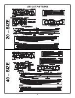
Page 5: ...5 DIE CUT PATTERNS 20 SIZE 40 SIZE...

Page 6: ...re it fully cures 1 Trial fit the die cut 3 32 balsa upper float side lower float side and aft float side Make adjustments if necessary When satisfied with the fit use thin CA to glue the three pieces...

Page 7: ...eck from former C forward 5 Lay waxed paper over your flat building board and position all the formers except A and I on the deck Make sure the notches in the formers fit all the way down to the deck...

Page 8: ...ng photo 3 Cut a 3 16 x 3 16 forward stringer to fit in the notches of formers E to A do not attempt to bend the stringer down to the notches in former A at this time Use a pen to make marks every 1 2...

Page 9: ...the center and should be placed so it covers half of the keel Make adjustments if necessary and bevel the edges of the aft bottom sheets that contact each other in the center Note An embossed arrow i...

Page 10: ...d arrows to aid in final alignment 4 Referring to the sketch rough sand the entire float with a sanding block and 150 grit sandpaper blending the sides to the deck and the bottoms to the side Sand all...

Page 11: ...rototype 60 floats mounted on our Great Planes J 3 Cub 60 are covered with MonoKote film and were really put to the test Following are instructions for both covering methods 1 Seal all seams except ar...

Page 12: ...ing you may do the top and sides first then the bottom If you work quickly you can save the paint brush by cleaning it with alcohol before the resin begins to thicken 7 Carefully sand the entire float...

Page 13: ...this yields a slight positive wing incidence in relation to the floats and the airplane will tend to rise off the water at the correct time If you have a model with a symmetrical wing the wing incide...

Page 14: ...solder 1 Match the shorter front strut with the front cross brace and the taller rear strut with the rear cross brace The matching struts and cross braces are the ones that fit together the best Note...

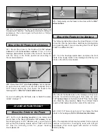
Page 15: ...hem with a 12 or 13 64 drill bit Mount the bearings to the floats with 4 40 x 1 2 screws 2 Temporarily join the floats to the struts by inserting them into the bearing mounts Use a felt tip pen to mar...

Page 16: ...per bearing mount placement 2 Temporarily join the floats to the struts with the 5 32 wheel collars The following instructions show the Great Planes J 3 Cub 20 and 40 Use the instructions sketches and...

Page 17: ...n the nylon swivel 1 8 past the end 4 Loosely install the rudder on the right float with two flat straps two 1 8 hump straps and four 2 x 3 8 sheet metal screws Adjust the bottom of the rudder bracket...

Page 18: ...de tube to the aft strut with a nylon tie 8 Drill a 1 16 hole and secure the cable guide tube to the mount plate with one of the cut off hump straps and 2 x 3 8 sheet metal screws 20 40 Floats only Af...

Page 19: ...rewing the nylon clevis at either end of the cable 8 Mount another 1 8 plywood mount plate and the other cut hump strap near the rear of the guide tube 9 Test the actuation of the water rudder on the...

Page 20: ...g around in the water to learn the handling characteristics and see if you have built in enough throw on the water rudder Make adjustments if required During taxiing hold up elevator to keep the nose...

Page 21: ......

Reviews: