background image

Sportster Bipe

40

Instruction Manual

Engine size

.35-.45

Wingspan

45  1/2"

Length                          41 1/2"

Wing Area

716 sq

.

in.

Weight

5 - 6 1 / 2

Ibs.

Materials Needed to  Complete the Sportster:

4

Channel radio 

Propeller 

Fuel tank 

Engine Wheel 

collars

Spinner

Fiberglass cloth/resin

Wheels

Covering

Engine mounting bolts

Hinges Instant 

glue

Pushrods/clevises

Wing bolts

EPOXY

The Sportster Bipe 40 was designed for sport flying. This biplane design with  symmetrical wings  pro-

vides full aerobatic maneuverability, yet  has enough wing area for docile low speed capability.

The parts are machine cut and sanded for accurate fit. Should you notice a difference in size between 

plans and parts, it is usually because paper changes size with moisture.

Different types of glue may be used such

as epoxy, cyanoacrylate(instant glue) and aliphatic resin (white 

glue). Build on a flat surface for straight wings and fuselage. 

Please read through this step-by-step instruction manual before you start building 

so you will have an

overall idea of  the  construction  steps and to avoid mistakes. Use the plan and parts list to identify the var-

ious parts.

WAR

N

I

N

G

!

This R/C kit and the model you will build is not a toy! It is capable of serious

bodily harm and property damage.

IT

IS

YOUR RESPONSIBILITY AND  YOURS

ALONE

-

to build this  kit correctly, properly install all  R/C components and flying

gear (engine, tank, pushrods, etc.) and to test the model and fly

it

only

with experi-

enced, competent help in accordance with all safety standards and common
sense as set down in the Academy of Model Aeronautics Safety Code.

It

is sug-

gested that you join the AMA and become properly insured before you attempt to
fly this model. IF YOU ARE JUST STARTING R/C MODELING, CONSULT YOUR

LOCAL HOBBY SHOP OR WRITE TO THE ACADEMY OF MODEL AERONAUTICS

TO

FIND AN  EXPERIENCED INSTRUCTOR IN YOUR AREA.

Academy of Model Aeronautics 

1810 Samuel Morse Dr.
Reston, VA

22090

P O

BOX

788

URBANA

lLLlNOlS61801

2171367

2069

Summary of Contents for Sportster Bipe 40

Page 1: ...d fuselage Please read through this step by step instruction manual before you start building so you will have an overall idea of the construction steps and to avoid mistakes Use the plan and parts li...

Page 2: ...f the rudder leading edge for elevator joiner wire clearance Wait to shape the leading edge until the hole is drilled for the tail wheel tiller arm later 3 GLUE STAB PARTSTOGETHER SANDTHE STAB AND ELE...

Page 3: ...RST BEFORE YOU START BUILDING THE WING PANELS It isvery important that you buildstraight wings with nowarps or twists or youwill get someflying characteristics you didn t expect Bevery carefulwhen you...

Page 4: ...s to the building board glue the ribs to the spar Line up the lines on the ribs with the line on the leading edge Glue the ribs to the leading edge Line up the trailing edge line to the rib lines and...

Page 5: ...and cut pieces to fit along the length of the cabane holders as shown on the plan Glue this 1 4 tri to the sheeting and to the cabane holder Also cut tri stock to fit on either side of the three cent...

Page 6: ...to the spar Use the 1 4 x 7 8 x 3 wing hold down block as a spacer for location of ribs 1 and 2 Note These hold downs are the same size as the ones that glue into the fuselage later Do not glue the h...

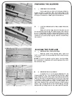
Page 7: ...he lower end of the wing tips top and bottom Sand this filler to shape later after hinging and installing the ailerons Sand the leading edge to the rounded shape shown on the plans Cut off thesparsand...

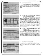
Page 8: ...the panels Use a straight edge to make sure the leading edge of the wing is straight Block up the wing 7 8 at the center and glue the panels together using slow set epoxy See the drawing on the plan R...

Page 9: ...SIDES Mark the inside of the fuselage sides right and left Cut out part of the wing saddle area at the rear as shown on the plan STOP If you plan to install a 4 cycle engine read and follow the instr...

Page 10: ...Make push rod braces from scrap 1 8 x 3 x 36 left over from the doubler stock in the step you just did The widths of the braces are the same as that of each of the formers The braces will be installe...

Page 11: ...9 GLUE LEFT FUSELAGE SIDE TO THE BUL KHEADS Align the fuselage sidelbulkhead assembly upside down over the top view of the plans Make sure the flat side is resting flat on the building board and that...

Page 12: ...e should butt up to the doubler Pin the deck base over the plans to your work surface Mark the location of Formers 4 5 and 6 Check the fit of the formers and glue them to the deck base making sure the...

Page 13: ...en where the tail wheel strut mounting tab will glue later glue the fuse sides together at the tail 17 GLUE PUSHROD BRACESTO FORMERS GLUE PUSHROD HOUSINGSTO BRACES Using the pushrod housings as guides...

Page 14: ...o thefuselage Thefuselage is not shown aligned to the plans in the photo 21 ADD THE BALSA BOTTOM SHEETING With all pins removedfrom the insideof thefuselage cross grain sheet the bottom rear of the fu...

Page 15: ...t glue on the hoodtop yet Glue former 3A 3B tothefuselageatthe rearof the cockpitontopof bulkhead 3 25 GLUE IN THE COCKPIT FLOOR Glueinthe balsa cockpit floor between the dash and former 3A 3B on the...

Page 16: ...and cuts down on vibration After the wing is covered later you will attach the top wing to the cabanes with the aluminum plates and the 2 x 3 8 screws provided Ttie plates should be flush with the wi...

Page 17: ...ttle difficult to sand in that area after the hood top is glued on Glue the hood top in place Trim the hood sides at the cockpit as shown on the plans 33 ADDFORMER6A 6B Pin the stabilizer in place so...

Page 18: ...ce Using 5 minute glue the nose side blocks in place Remove excess epoxy at the chin blockjoint Carve and rough sand the hood top hood sides and chin block to the shape of the nose side pieces The nex...

Page 19: ...these pieces so they glue to the firewall and nosefiller block Now sand and carve the nose of the fuselage to the shape of the spinner ring 41 DRILL FUEL LINE HOLES AND A DRAIN HOLE Drill the holes in...

Page 20: ...eces are used to anchor the covering material later 45 ADD TAIL WHEEL STRUT FINISH RUDDER Glue the tail wheel strut in place as shown on the plans Use 5 minute and clamp the tail until dry Add the las...

Page 21: ...to install the wing fairings by drawing lines on the bottom of the wing even with the fuselage sides Cut the fairings to width Sand to shape by placing sandpaper on the wing and working the fairings...

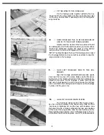
Page 22: ...s to the ailerontorque rod arms with the nylonconnectors wheel collars and screws provided and clevises of your choice This end of the linkage is therefore adjustable 9 INSTALLTHE MAIN GEAR Placetheso...

Page 23: ...ning Cut out this area Findthe tape locationson the insideof the pant in Figure 1 Use 60 100 coarse sandpaper and sand the areas where you will put the tape Reinforce the inside of the wheel pants wit...

Page 24: ...Cycle combination is unbeatable Four cycle engines offer many benefits theirquiet realistic sound is pleasingto modelers and non mod elers alike Hightorque allows the useof highpitchor largediameter p...

Page 25: ...MOUNT...

Page 26: ...HAYES AL 60...

Page 27: ...washer Measure back from this straight edge to the back of the mount This is distance B Refer to the drawings and the chart shown here We are measuring this distance so we can determine how far back...

Page 28: ...extend past Bulkhead 3 Carefully trim the doublers to the fuse side shape 11 GLUE FIREWALL IN CORRECTED POSITION Draw the corrected bulkhead 1 positionon the top view of the plans Next still working o...

Page 29: ...1 2 propeller Four cycles like flywheel weight from large diameter props This made the plane land a little faster than with the 11 x 6 The prop we used was a prop designed for 60 size pattern engines...

Page 30: ...2x3 1 4 Wing Plate SB40A02 1 Sub Pack Fuselageand Wing Parts SB4OF34 1 Balsa118x3 4x3 FalsaBulkhead NoseFillerBlock SS4OF16 1 Balsa2 1 4x2 1 4x 1 2 SS4OF18 1 Balsa1 4 Former1A SS4OF19 1 Balsa1 4 Forme...

Page 31: ...I Use trim MonoKote and these letters to create your trim scheme on your Sportster...

Page 32: ...e sketch Measure Throw Here I The best way to balance your Super Sportster is to make a Balancing Stand from a square of 1 4 plywood and two 3 8 dowels Markthe foreand aftlimitsof thebalancerangeon th...

Reviews: