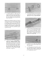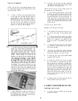
WARNING: Do not omit this next important
step!
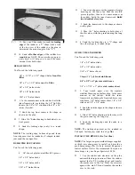
D 23. Cut two pieces of 3/8" balsa triangle to fit
between F-6 and the tapered balsa tail filler,
at the joints between the fuse sides and the aft
deck base. You will have to taper the ends of
these triangle pieces to fit properly, as shown
on the fuse plan top view. Working through
the opening in the fuse bottom, glue these
pieces securely in place.
INSTALL REAR PUSHROD GUIDE TUBES
IMPORTANT NOTE: Before proceeding, plan your
servo and pushrod installation. Especially note
which side of the fuselage the throttle pushrod and
nose gear pushrod (if any) will be located. Remember
that the throttle arms of 2-cycle and 4- cycle engines
are on opposite sides. It will be helpful to actually
sketch your pushrod locations on the plans with a
pencil.
D 1. Sand the outer surface of the pushrod guide
tubes with 100 grit sandpaper to provide a
surface to which the glue will adhere.
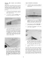
D 2. Use an Xacto knife to sharpen one end of a
piece of 3/16" (outside diameter) brass tubing,
then use this tubing to cut the pushrod exit
holes. Determine the location of these holes
from the plans. Note that each elevator re-
quires a separate pushrod.
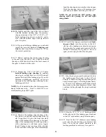
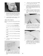
D 3. Insert the plastic pushrod tubes through the
holes you just cut and through formers F-6,
F-5, F-4 and F-3. Cut grooves in the inside
opening of F-6 at the pushrod tube locations to
minimize the curvature of the tubes.
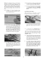
4. Route the pushrod tubes according to your
radio installation plan, and anchor the tubes
to formers F-4, F-5 and F-6 using 1/8" x 3/8"
balsa cross- braces. Keep tubes as straight
as possible. Do not anchor the tubes to F-3
at this time, to allow for slight adjustment of
the position of the pushrods when the servos
are installed later. Leave approximately 2 in-
ches of the pushrod tubes protruding into the
radio compartment, and cut off the excess.
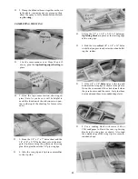
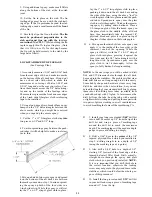
D 5. Glue the pushrod tubes to the fuse sides at
the exit points, using thin CA glue. Then cut
off the tubes and sand them flush with the fuse
sides using a sanding block.
20


