background image

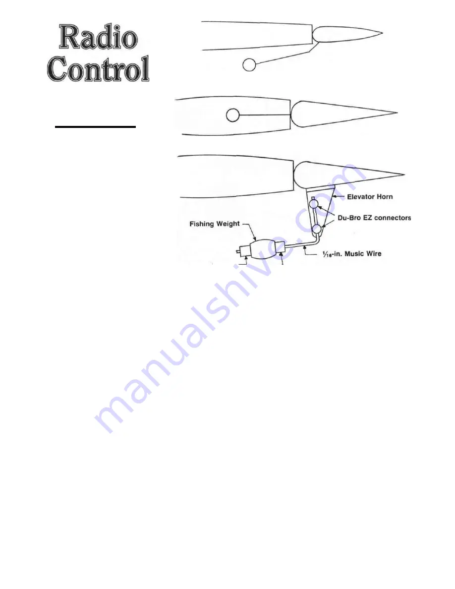
Figure 1. Balancing a control surface eliminates flutter. Putting the mechanism outside is

easiest, but there are drawbacks: not very pretty, and the hardware can catch on things.

Sport and

Aerobatics

Ron Van Putte

111 Sleepy Oaks Rd.

Ft. Walton Beach, FL 32548

PERIODICALLY I read in aircraft design arti-

cles about how to "prevent" control surface

flutter In most cases the suggestions are good
ideas to use in delaying the onset of the
phenomenon, but few actually work in prevent-
ing
 flutter

Before I get into the subject further, there are a

few things which need to be clarified First, in
the classical sense, what modelers usually call

control surface flutter isn't flutter at all but con-
trol surface buzz Flutter engineers reserve the
word "flutter" to describe oscillatory, self-
sustaining motion of aircraft components which
involves the interaction of two or more modes of
component motion Control surface buzz in-
volves only one mode of aircraft component
motion Big deal, right

9

To a  f l u t t e r engineer the  d i s t i n c t i o n is

important, because it describes a completely dif-
ferent mechanism of interactions To modelers

the distinction is usually not important because
we seldom observe classical flutter

Flutter is inherently destructive At the flutter

speed, aircraft components bend and/or twist in
sustained oscillations whose amplitudes neither

decrease or increase However, once the flutter

speed is exceeded, the oscillations grow in ampli-
tude until something breaks or otherwise changes
the relationships among the affected aircraft

components (Many modern fighters must be

loaded with external stores very carefully be-

Figure 2. Another way to mass-balance a control surface. Neat, but hard to make.

Vie-in. Wheel Collars —J——————

l

Figure 3. Bowing to the inevitable—do it the easiest way. Here's a suggested set of common
materials to use for a neat, functional job of statically balancing a control surface.

trol surface buzz, I'm going to turn around and
call it control surface flutter anyway, because
that's what most of us call it This kind of motion
involves only oscillatory rotation of the aileron or

elevator It is caused by the way we hinge them
and the way we move them

Since they are hinged at the front, the center of

mass of the surface is behind the hinge point
They are often moved via a torque rod which en-
ters the inboard end of the surface It is the com-
bination of these two design features which pro-

duces control surface flutter, and once you have
them, there is a speed at which you will have

make the control surface torque rod suffer This

causes the natural frequency of aileron rotation to

increase, which causes flutter to occur at a higher
airspeed

However, suppose you try both these tech-

niques, and you still have flutter Is there any-
thing else which can be done

9

 Yes, there are a

few possible correctives, like removing the con-
trol surface and replacing it with one that is thick-
er at the leading edge than the trailing edge of the
wing or horizontal tail it is attached to You can

also make the trailing edge of the control surface

more blunt Both of these fixes also tend to in-

Back In his February 1988 column, author Van Putte suggested that one way to get differential aileron travel was to bend the aileron horn

forward. Some people felt that this would do no good, so Ron drew this sketch to prove his point. The radiuses to the arc (R) represent the
control horn position as the servo (L) gives equal Up and Down inputs. There is a noticeable difference in control horn travel between the Neu-
tral position and Up compared to the travel from Neutral to Down. (This sketch illustrates the aileron horn on a low-wing airplane.)

Neutral Down

cause their thin, flexible wings are potential flut-
ter victims )

I have observed only one case of model flutter

It happened to me on an early version of the Sen-
ior Falcon The original wing design was much
less rigid in both bending and torsion than the
present wing, and my aircraft went into a classi-
cal case of wing bending/torsion flutter at the bot-
tom of a near-vertical dive The right wing sepa-
rated from the aircraft about where the wing
sheeting ended Senior Falcons don't fly too well
with little more than half a wing

Now, having pointed out that control surface

flutter isn't really flutter at all but is actually con-

50 Model Aviation

flutter If you're lucky, the flutter speed is faster

than the airplane is capable of achieving In that
case, you'll never have flutter, and this is why
some of the techniques to "prevent" flutter are
successful

The two most common flutter-prevention tech-

niques work on opposite ends of the problem.
The easiest to implement is sealing the gap be-
tween the control surface and the wing or horizon-

tal stabilizer This attacks the aerodynamic driver

of the flutter problem and will cause flutter to oc-
cur at a higher airspeed. The second fix is to

43

Summary of Contents for Super Sportster 120

Page 1: ...ectly properly install all R C components and flying gear engine tank pushrods etc and to test the model and fly it only with experi enced competent help in accordance with all safety standards and co...

Page 2: ...KUPS AND CHECKS 38 PRE FLIGHT 39 CHARGE THE BATTERIES 39 FIND A SAFE PLACE TO FLY 39 GROUND CHECK THE MODEL 39 RANGE CHECK YOUR RADIO 39 ENGINE SAFETY PRECAUTIONS 39 AMA SAFETY CODE 39 FLYING 40 PARTS...

Page 3: ...dmodel andnorepresentations are expressed or implied as to the performance or safety of your completed model Remember Take your time and follow di rections to end up with a well built model that is st...

Page 4: ...elevator servos SUPPLIES AND TOOLS NEEDED 2 3 oz Thin CA Adhesive Pliers 2 oz Medium or Thick CA Adhesive Screw Driver 2 5 oz 5 Minute Epoxy T Pins 2 5 oz 30 Minute Epoxy Straightedge Hand or Electric...

Page 5: ...x1 2 SCREW 6 x I SCREW NYLON HORN AND NUT PLATE RETAINER CUP 2 56 x 5 8 SCREW 5 32 COLLAR 1 4 20 NYLON BOLT 4 40x1 BOLT HOLES TO BE DRILLED 6 32 x 1 4 SCREW 10 32 SOCKET HEAD CAP SCREW BRASS AILERON H...

Page 6: ...R DOUBLERS SS90W33 BALSA 3 32x4x18 8 PER KIT SS90W34 BALSA 3 32x4x18 3 PER KIT TAIL FEATHERS NOTE The Rudder Fin Elevators and Stabilizer are all built in a very similar manner The following section e...

Page 7: ...y openjoints then useyour T bar with medium grit sandpaper to sand both sides of the rudder framework smooth 7 From the 1 16 x 3 x 36 balsa sheets cut four pieces 12 long Edge glue these pieces togeth...

Page 8: ...wer front edge must not be rounded or V shaped instead just sand these edges flat BUILD THE ELEVATORS You ll need the following parts 4 1 8 die cut ply elevator filler EF pieces 1 4 x 3 4 balsa sticks...

Page 9: ...ns Ifyou are buildingyourplane as ataildragger cut out the front notches in the W 2 ribs If you are building your plane with a tricycle gear cut out the rear notches Trim the die cut 1 16 ply doublers...

Page 10: ...a notch for the W 1 rib Use the 1 8 die cut ply dihedral gauges DGR and DGL to position rib W 1 at the proper angle When building the right wing panel use dihedral gauge DGR to position W 1 setting th...

Page 11: ...ting by sanding one edge to a slight bevel so it will fit snugly against the back of the leading edge Ifyou are building a taildragger carefully cut out an opening in the leading edge sheeting for the...

Page 12: ...rib at this time D D 27 Carefully cut out the center portion of the W l ribs 1 8 in front and back of the spars tomakeroomfortheplywooddihedralbraces D 28 Now go back and repeat steps 5 through 27 to...

Page 13: ...the photos Do not be concerned if the sticks break when they are bent around the curve Just glue them down and sand them to a rounded shape later D 2 Glue the top center section sheeting in place Note...

Page 14: ...turbing D 6 Drill holes in the flattened portion of the brass horn for the clevis pin Note The proper size drill bit to use here is a 53 bit available at most hardware stores You may however use a 1 1...

Page 15: ...rap the glass cloth around the trailing edge D 5 Working outdoors or in a very well venti lated area apply thin CA glue to the glass cloth Begin by running a bead of glue down the center ofthe glass c...

Page 16: ...finally go back and complete the push in the original position Clean out the slot with the slotting hook D 9 IMPORTANT Condition or break in the hinges by folding them tightly back and forth several t...

Page 17: ...e front edge of the fuse side A good way to do this is to carefully align the fuse doublers and while holding in position apply thin CA glue around the notches and lightening holes then around the edg...

Page 18: ...he hold down block D 10 Position former F 4 in place between the lines on the aft deck base and center it side to side Glue F 4 to the aft deck base while using a draftsman s triangle or carpenter s s...

Page 19: ...in the front of the fuse doubler at the end of the engine mounting rail slots 18 If you plan to use the hardwood engine mounting rails supplied in this kit trial fit the rails through the openings in...

Page 20: ...will adhere D 2 Use an Xacto knife to sharpen one end of a piece of 3 16 outside diameter brass tubing then use this tubing to cut the pushrod exit holes Determine the location of these holes from the...

Page 21: ...ne up with F 2 and the front ofthe wing saddle area Position the chin block so it protrudes 1 8 behind the rear surface of F 2 and so the centerline of the chin block lines up with the centerline of t...

Page 22: ...he holes in the wing only to 1 4 D 14 Use a 1 4 20 tap and a tap wrench to cut threads in the ply hold down blocks in the fuselage Note To help get the tap started straight you may keep the wing in pl...

Page 23: ...nd nuts D 4 Install the blind nuts in the bottom of the hardwood rails Note that part of the blind nut flanges protrude into the engine mounting area Trial fit your engine to find out if the protrudin...

Page 24: ...tank support Adjust the position of the tank up or down by adding foam as necessary until the center of the tank is approximately at the same level as the fuel intake on the carburetor D 4 Drill hole...

Page 25: ...ce of F 2D D 5 Glue F 3A to F 3B and F 6A to F 6B D 6 Lay the F 6A and F 6B assembly on the F 6 detail drawing and mark the location of the center of each rear stringer on F 6A D 11 Glue the 3 8 balsa...

Page 26: ...straightedge and an Xacto knife trim the sheeting along the center of the top stringer D 4 Apply thick CA to the tops of the formers and stringers apply glue only to 1 2 of the top stringer then imme...

Page 27: ...kplate fully against the thrust washer be cause the chin block is slightly too long Re move the spinner backplate and using a sand ing block sand the front of the chin block slightly Repeat this proce...

Page 28: ...er filler block the chin block and to the engine mounting rails if applicable 10 Cut pieces of 1 2 balsa triangle to fit in the corners of the engine compartment where shown and glue in place SAND THE...

Page 29: ...ng block in position pushing down to imprint the locations of the 1 16 ply wing hold down plates on the fairing block Carve the fairing block to clear the wing hold down plates D 5 Make a 1 2 deep saw...

Page 30: ...fuse and the stabilizer D 5 Accurately measure the trailing edge of the stabilizer and mark the center point D 6 Temporarily mount the wing in the saddle for reference D 7 Lay the stab in position on...

Page 31: ...2 teaspoon glob of this thickened epoxy on the glass cloth in the middle of the aft deck base then immediately take the tapered 1 4 plywood block and press it in place on top of the glass cloth as sh...

Page 32: ...ck CA glue per block D 6 Temporarily attach the elevators and rudder to check their fit and operation IMPORTANT NOTE When making the tricycle version you ll have to install a 4th rudder hinge in the l...

Page 33: ...to the fuse doublers and to the bottom edge of the 3 8 balsa hood sides in the area between F 3 and the 1 4 balsa cross brace D 2 Lay the two 3 16 x 1 2 x 4 3 32 ply servo rails on the rail supports s...

Page 34: ...you wish you can use solder clevises for the pushrod to servo linkage here D 6 Unscrew the metal clevises re insert the pushrods and replace the clevises Remove the servo wheels and work the Z bends...

Page 35: ...a flat table to sand the pants down to the trim line D 2 Clean the wheel pants halves with a tissue dampened with alcohol D 3 Lightly sand the inside of the wheel pants with fine sandpaper D 6 Cut the...

Page 36: ...not be covered and which may be exposed to glow fuel residue such as the landing gear block slots and the wing saddle Use epoxy thinned with alcohol polyester finishing resin or fuelproof paint BALAN...

Page 37: ...plastic soda straw then pinch the end of the straw insert it into the hinge slot and squeeze the straw to force glue into the slot Apply epoxy to the hinge then insert the hinge into the slot After p...

Page 38: ...ches to 4 inches back from the leading edge This is the balance point at which your model should balance for your first flights Later you may wish to shift the balance up to 1 2 forward or back to cha...

Page 39: ...RANGE CHECK YOUR RADIO Wherever you do fly you need to check the operation ofthe radio before every time you fly This means with the transmitter antenna down and the receiver and transmitter on you sh...

Page 40: ...e downwind leg of the landing approach This will automatically help to bleed off some of the speed If you have trouble getting your big engine to idle down slow enough to land at a comfortable speed w...

Page 41: ...Rails 3 Ply 1 32x 1x1Spinner Ring Spacer 3 Ply 1 8X3 8X3 5 8Servo Rail Supports 5 Ply 1 4x1x1 Stab Reinforcement Block 5 Ply Shaped 1 4 Front Stab Brace 5 Ply 1 4x1 2x6 Rear Stab Brace Hardwood 5 16Di...

Page 42: ...x 12 3 4 Front Stringers SS90F23 1 Hardwood 1 4 x 1 4 x 19 3 4 Top Rear Stringer SS90F24 8 Hardwood 3 16x3 16x19 3 4 Rear Stringers PART QTY DESCRIPTION SS90A12 SHEETING BalsaShaped1 8Aft SS90F02 SS90...

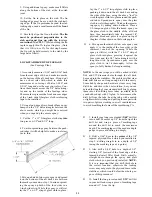
Page 43: ...ard end of the surface It is the com bination of these two design features which pro duces control surface flutter and once you have them there is a speed at which you will have make the control surfa...

Page 44: ...ded for ease of installation struc tural integrity and the ability to change weights What you must do is get the balance weight large enough to cause the control surface to bare ly move up when it is...

Page 45: ...h sides of the fuselage and place the airplane upside down on the balancing stand as shown in the sketch empty fuel tank Move the airplane forward or aft on the stand until it balances with the stab l...

Reviews: