7
At this stage the model should be in ready-to-fl y condition
with all of the systems in place including the receiver, ESC,
and battery pack.
❏
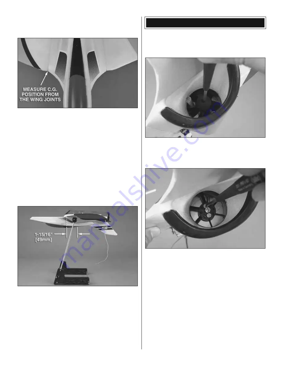
1. Use a felt-tip pen or 1/8" [3mm]-wide tape to accurately
mark the C.G. on the top of the wing on both sides of the
fuselage.
The C.G. is located 1-15/16" [49mm] back from
the leading edge of the wing at the fuselage (the seam
where the wing panels have been joined to the fuselage).
This is where your model should balance for the fi rst fl ights.
Later, you may wish to experiment by shifting the C.G. up to
1/8" [3mm] forward or 1/8" [3mm] back to change the fl ying
characteristics. Moving the C.G. forward may improve the
smoothness and stability, but the model may be more diffi cult
to slow for landing. Moving the C.G. aft makes the model
more maneuverable, but could also cause it to become too
diffi cult to control. In any case, start at the recommended
balance point and do not at any time balance the model
outside the specifi ed range.
❏
2. With all parts of the model installed (ready to fl y), place
the model upside-down on a Great Planes CG Machine, or
lift it upside down at the balance point you marked.
❏
3. If the tail drops, the model is “tail heavy” and the battery
pack and/or receiver must be shifted to balance. If the nose
drops, the model is “nose heavy” and the battery pack and/or
receiver must be shifted to balance. This model is very weight
sensitive. Do not add any weight to achieve the suggested
balance point. Instead, shift the battery pack and receiver
forward or aft to alter the C.G.
PREPARE TO RUN THE FAN
This is a high performance EDF. We strongly advise
checking the EDF fan and motor mounting screws on a
regular basis.
1. Insert a wood dowel through the exhaust duct and through
the fan rotor in order to prevent the rotor from turning without
damaging it. Remove the rotor screw and washer. Extract the
rotor cone and the fan rotor from the plane.
2. Remove the motor mounting screws and washers, apply
threadlock (or a drop of CA glue) and replace. Tighten fi rmly.
3. Apply threadlock on the rotor screw and reinstall the
fan assembly.
BEFORE YOU RUN THE FAN MAKE SURE THAT:
• The motor selected is one of the recommended motors.
• An appropriate ESC is being used.
• An appropriate LiPo battery is being used.
• All the screws and set screws are secured with threadlocking
compound.
• All the fan parts are properly attached to the fan and to
the airframe.
• If any part of this fan should become damaged, replace all
parts. Never attempt to repair damaged parts.


