removed, use a vinyl tape to attach the fuel tank to the fuel
tank tray. As you insert the fuel tank into the fuel tank
compartment, route the fuel tubing out of the firewall. If the
tank is to be removable, attach the fuel tank tray to former
F-2 with two #2 x 3/8" screws. Attach the proper fuel tubes
to the engine and muffler.
❏
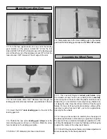
4. Lightly sand a strip approximately 1/8" wide along the
inside of the windshield (around the perimeter). Note: To
avoid sanding more than you want, it is helpful to first apply
strips of masking tape on the inside of the windshield, 1/8"
in from the edge.
❏
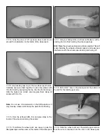
5. Hold the windshield in place on the fuselage. Use a fine
tip marker to trace the outline of the windshield onto the
covering. Remove the windshield and use a sharp #11
blade to cut a 1/8" strip from the covering just inside the line
you drew. A sharp blade is important so you do not have to
use much pressure. It will allow you to cut only the covering
and not the underlying wood.
❏
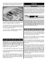
6. Carefully glue the windshield in place with a “canopy
glue,” such as Pacer Formula 560 Canopy Glue. We do not
recommend CA, as it may fog the plastic. Use masking tape
to hold it in place while the glue dries.
❏
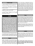
7. The side windows are cut from the 4" x 4" butyrate
sheet. Trim the windows to fit along the inside of the cabin
side. After the windows have been trimmed to fit, glue them
in place with a glue compatible with butyrate.
❏
8. The Taylorcraft kit contains a decal sheet including the
small emblems and the checkerboard on the tail which
would be difficult to reproduce otherwise. These decals are
the “peel-and-stick” type. Cut around the individual decal
emblems, peel off the protective backing, and apply them to
your airplane.
❏
1. Reinstall the rudder and elevator control horns, pushrods,
receiver, receiver battery, servos and receiver switch.
Important: Slide the silicone clevis retainers over all the
clevises before connecting the clevises to the control horns.
❏
2. Make a strain relief from a cut-off servo arm and place
it on the antenna where the antenna exits the fuse. Route
the receiver antenna out of the fuse. Anchor the antenna to
the top of the fin with a rubber band and T-pin.
Note: Do not shorten the antenna! Leave any excess
trailing behind the model.
Note: This section is VERY important and must NOT be
omitted! A model that is not properly balanced will be
unstable and possibly unflyable.
❏
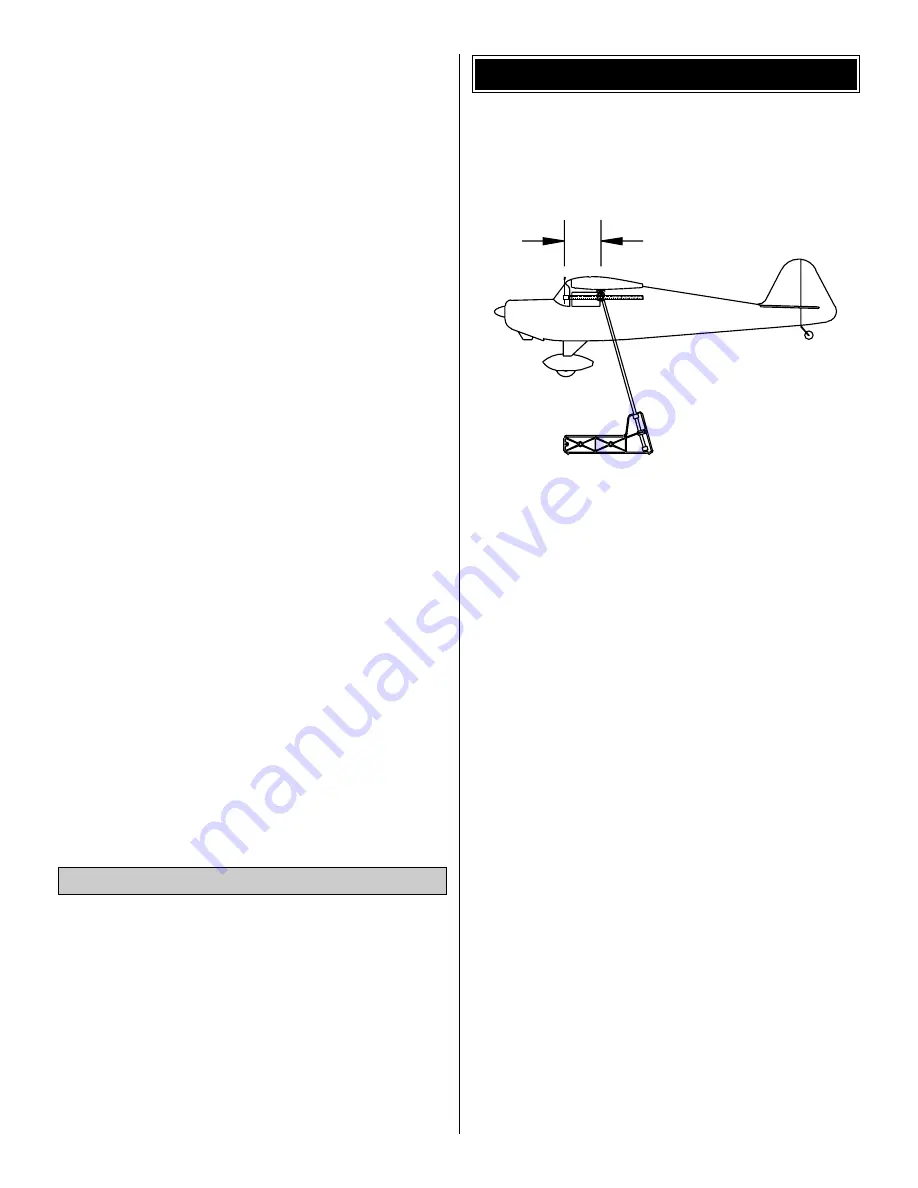
1. Accurately mark the balance point on the bottom of the
wing on both sides of the fuselage. The Great Planes C.G.
Machine
™
Airplane Balancer makes balancing your plane
easy and exact. The balance point (C.G.) is shown on the
fuse plan, and is located 3" back from the leading edge of
the wing. This is the balance point at which your model
should balance for your first flights. After initial trim flights
and when you become more acquainted with your
Taylorcraft, you may wish to experiment by shifting the
balance up to 1/4" forward or backward to change its flying
characteristics. Moving the balance forward may improve
the smoothness and stability, but the model may then
require more speed for takeoff and may become more
difficult to slow down for landing. Moving the balance aft
makes the model more agile with a lighter, snappier “feel.” In
any case, please start at the location we recommend.
Do not at any time balance your model outside the
recommended range.
❏
2. With all parts of the model installed (ready to fly) and
the fuel tank empty, lift the model at the balance point. If the
tail drops, the model is “tail heavy” and you may want to
move the receiver battery forward to balance the model. If
the nose drops, it is “nose heavy” and you may want to move
the receiver battery toward the tail to balance the model. It
is best to try balancing the plane by moving the receiver and
receiver battery.
* If you are unable to obtain good balance by moving the
receiver and receiver battery, then it will be necessary to add
weight to the nose or tail to achieve the proper balance point.
3"
BALANCE YOUR MODEL
Reinstall the Radio System
44


