13
❏
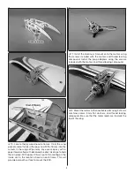
4. Fit the vertical fi n and horizontal stabilizer into place.
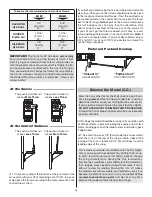
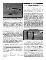
Use a felt tip marker to trace around the fuselage onto the tail
parts top and bottom and left and right side. Trace around the
fi n onto the fuse. Remove the tail parts and trim the covering
away 1/16" [1.6mm] inside your lines as shown.
HOW TO CUT COVERING FROM BALSA
Use a soldering iron to cut the covering from the stab. The
tip of the soldering iron doesn’t have to be sharp, but a
fi ne tip does work best. Allow the iron to heat fully.
Use a straightedge to guide the soldering iron at a rate
that will just melt the covering and not burn into the wood.
The hotter the soldering iron, the faster it must travel to
melt a fi ne cut. Peel off the covering.
❏
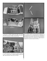
5. Re-insert the horizontal stabilizer and vertical fi n into
the fuse. With the wing in place, stand behind the model
approximately 10 feet [3m] and confi rm that the stab sits
parallel with the wing. If not, weight can be added to the high
side while gluing the stab in place, or the stab pocket can
be lightly sanded until the stab and wing sit parallel. When
satisfi ed, remove the stab and fi n and coat the exposed
wood with 30-minute epoxy (although messy, a more reliable
glue joint can be attained if you also coat the inside edges of
the stab pocket). Reinstall the stab and fi n. Wipe away any
excess epoxy with denatured alcohol and let the epoxy cure
undisturbed. When cured, the wing can be removed from
the fuselage and set aside as it will not be needed until the
fi nal set up of the plane.
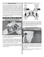
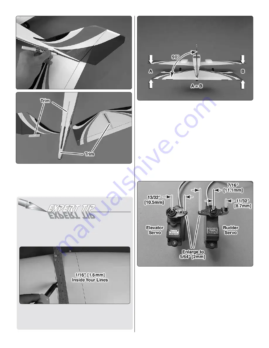
Install servo arms onto the elevator and rudder servos as
shown. A brass screw lock connector is needed for the
nose gear pushrod. Enlarge the holes for the rudder and
elavator pushrods using a 5/64" [2 mm] drill bit. We chose
a high torque servo for the rudder for more responsive yaw
control in fl ight.


