7
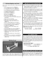
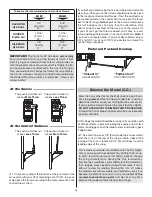
their best orientation so that the arms are closest to being
perpendicular with the servo case. Cut three arms from each
servo arm leaving one arm on each servo that matches the
photo. Enlarge the hole closest to 9/16" [14.3 mm] to the
center of the servo arm of each remaining arm with a 5/64"
[ 2 mm] drill bit. Attach a 12" [ 305 mm] servo extension to each
servo. Secure the connection using the pieces of included
heat shrink tubing. Install the rubber grommets and eyelets
onto the servo mounting tabs.
❏
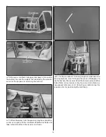
2. Tie the string ends that are taped inside the wings at
the aileron servo bays to the servo extension connectors.
❏
3. Pull the strings through the root ribs. Be careful not to
damage the wing ribs as you pull the servo leads through them.
❏
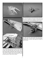
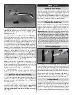
4. Fit the servos into the servo openings and drill 1/16"
[1.6mm] holes through the mounting tabs on the servo cases
into the rails. Thread a servo mounting screw (included with
the servo) into each hole and remove it. Apply a drop of thin
CA to each hole to harden the surrounding wood. When the
CA has hardened, install the servos into the openings as
shown using the screws supplied with the servos.
❏
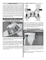
5. Thread a nylon clevis onto two 6" [150mm] aileron
pushrods 20 complete turns.
Hinge Line
Hinge Line
Correct
Incorrect
❏
6. Separate the back plates from two control horns using
a knife or sprue cutters. Connect the clevises on the aileron


