8
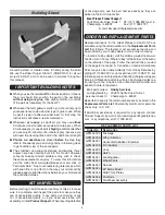
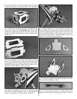
the control horns over the hardwood blocks in the ailerons
(if you cannot see them, hold the aileron at a shallow angle
in good lighting or use a small pin to puncture the covering).
When satisfi ed, use a felt-tip pen to mark the location of the
control horn mounting holes onto the aileron. Repeat this
step for the other aileron.
❏
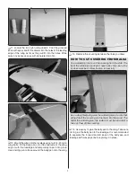
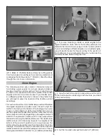
7. Drill 5/64" [2mm] holes at the marks you made. Thread
a #4 x 5/8" [16mm] self-tapping screw into each hole and
back it out. Apply a drop of thin CA to each hole to harden the
surrounding wood. Install the control horns onto the ailerons
using eight #4 x 5/8" [16mm] screws.
❏
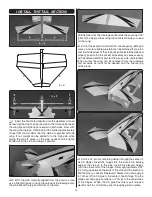
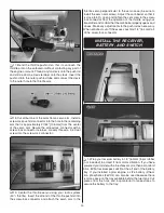
8. With the ailerons in the neutral position (use tape or
small clamps to hold them in place), mark the pushrod wires
where they cross the outer holes in the servo arms.
❏
9. Clean the area of the pushrods between the marks
you made and the threads with a paper towel dampened
with denatured alcohol. Apply a thin coating of epoxy onto
the pushrods from the end of the threads to approximately
3/4" [19mm] from your marks. Slide the two 4-1/8" [105mm]
carbon tubes over the pushrods up to the pushrod threads.
Wipe away any excess epoxy with denatured alcohol and
allow the epoxy to cure undisturbed.
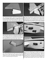
Servo Horn
1/16" [1.6 mm]
Pushrod Wire
FasLink
❏
10. Make a 90 degree bend at the mark on each pushrod
and cut off the excess pushrod 1/4" [6mm] ends beyond the
bends. Attach the pushrods to the servo arms using nylon
FasLinks. Thread the clevises up or down on the pushrods
as necessary to center the ailerons with the servo arms still
perpendicular to the servo cases. When satisfi ed, slide silicone
clevis retainers onto the ends of the clevises to secure them.


