D D 19. Slide a silicone retainer on the pushrod. Use a
5/64" or #48 drill bit to enlarge the hole in the control horn
on the bottom aileron only. Insert the "Z-bend" in the
control horn and attach the clevis to the control horn on the
aileron of the top wing. Slide the retainer over the clevis to
secure it to the control horn.
D 20. Assemble the other aileron pushrod following the
same procedure.
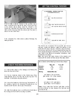
4-CHANNEL RADIO SETUP
(STANDARD MODE 2)
ELEVATOR MOVES UP
RIGHT AILERON MOVES UP
LEFT AILERON MOVES DOWN
RUDDER MOVES RIGHT
CARBURETOR WIDE OPEN
The throws are measured at the widest part of the
elevators, rudder and ailerons. Adjust the position of the
pushrods at the servo horns to control the amount of throw.
You may also use the ATV'S if your transmitter has them but
the mechanical linkages should still be set so the ATV'S are
near 100% for the best servo resolution (smoothest, most
proportional movement).
Note: We found that some mixing of the elevator and
aileron with the rudder will make flying knife-edges easier.
D 1. Mount both wings on the fuselage and block-up the
tail so that the stab is level.
D 2. Set an incidence meter on the bottom wing. Take
measurements next to the fuse and at the wing tips. The
incidence on the bottom wing should be 0°.
D 3. Check the incidence of the top wing. It should be 0°. If
the incidence needs to be changed, #6 washers can be
inserted under the 6-32 nuts on top of the cabane.
D 4. After the incidence is set, cut off the 6-32 bolts above
the locking nuts that hold the top wing in position.
We recommend the following control surface throws:
Elevator
Rudder
Ailerons
Mixing
High rate
5/8"
1-1/4"
1/4"
Rudder/Elevator
Low rate
7/16"
1-1/4"
3/16"
left rudder -1/8" up elevator
right rudder -1/16" down elevator
Rudder/Aileron
left rudder -1/16" right aileron
right rudder -1/32" left aileron
Note: If your radio does not have dual rates, set the
control surfaces to move between the high rate and
low rate throws.
43


