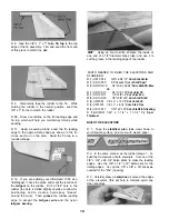
D 2 Sand one end of each of the medium and short
spars to a 2-1/2" taper as shown in the "Wing Spar
Detail" on the plan
D 3. Glue the medium spars to the long spars, and
glue the short spars to the medium spars, as shown
in the "Wing Spar Detail." Sand the edges of the
spars to remove any excess glue and to make the
edges uniform. Make four spar assemblies.
RIB DOUBLERS (Fixed Landing Gear -
TAILDRAGGER)
(Skip this section of you will be installing retracts)
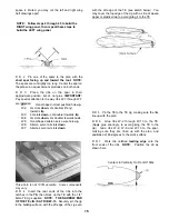
D 1 Identify the die-cut 1/8" ply landing gear
doublers for fixed taildragger, using the following
sketch:
RIBS
D 1. Carefully punch out all the die-cut balsa wing
ribs. Sand the edges slightly to remove any die-
cutting irregularities.
D 2. Note that the wing plan shows two alternate
locations for the main landing gear blocks Note also
that Ribs W-2, W-3 and W-4 have partial cutouts for
each of the two locations If you are building your
plane as a fixed gear taildragger, cut out the front
notches in these ribs If you are building your plane
with a tricycle gear, cut out the rear notches (If you
will be installing retracts, do not cut out any of the
notches).
RIB DOUBLERS (Fixed Landing Gear - TRIKE)
(Skip this section if your airplane is to be a taildragger)
D 1. Identify the die-cut 1/8" ply landing gear
doublers for fixed trike gear, using the following
sketch:
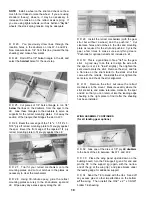
D 2. The doubler for rib W-2 has a notch cut out for
the landing gear block The doublers for ribs W-3 and
W-4 have the notch locations marked, and you must
now cut out these notches.
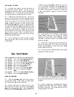
Do not cut out aft rib notches as shown in photo.
D 3 Glue these die-cut 1/8" ply landing gear doublers
to ribs W-2, W-3 and W-4 NOTE: Make a RIGHT
and a LEFT set, gluing the doublers to the inboard
side of the ribs. Take care to carefully align the
doublers with the spar notches The doublers are
slightly shorter than the ribs at the front edge, to allow
fitting into the leading edge notches.
Do not cut out front rib notches as shown in photo.
D 2. Glue these die-cut 1/8" ply landing gear doublers
to ribs W-2, W-3 and W-4. NOTE: Make a RIGHT
and a LEFT set, gluing the doublers to the inboard
side of the ribs.
RIB DOUBLERS (Optional Retractable Landing Gear)
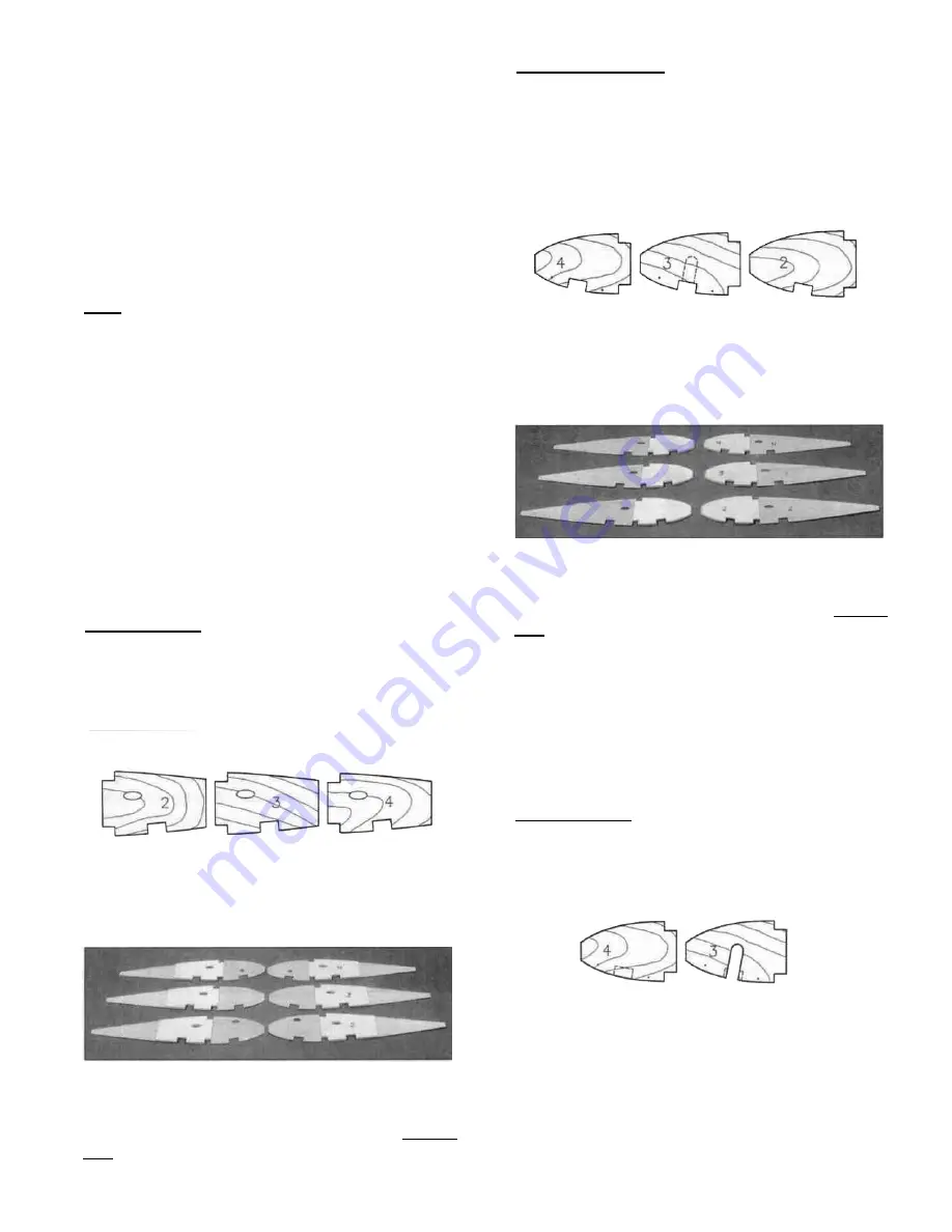
D 1. Identify the die-cut 1/8" ply landing gear
doublers for retracts, using the following sketch:
D 2. Note that these doublers have two small punch
marks. Push a T-pin through these marks so the
location is visible on both sides Now draw a line from
the front edge of each doubler to the back edge, using
the two small holes for alignment Draw the lines on
both sides These lines will later be used for
alignment of the retract mounting plates.
13

