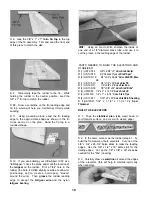
space is limited, you may cut the left and right wing
half drawings apart
with the aft edge of the TE (see sketch below) You
may cover the top edge of the Jig with a strip of waxed
paper or plastic wrap to avoid gluing it to the TE
NOTE: Follow steps 2 through 45 to build the
RIGHT wing panel, then repeat these steps to
build the LEFT wing panel.
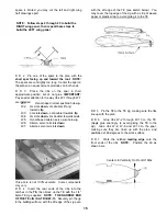
D D 2 Pin one of the spars to the plan with the
short spar facing up and toward the root. NOTE:
The spars are cut slightly too long Center the spar on
the plan so an equal amount protrudes on both ends.
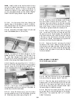
D D 3 Place the ribs on the spar in their
approximate position, but do not glue IMPORTANT:
Pay special attention to the way ribs W-1 through W-7
are installed ..
W-1: Oval-shaped retract pushrod hole up.
W-2: LG slots down, LG doubler (if any)
towards tip
W-3: LG slots down, LG doubler towards tip
W-4: LG slots down, LG doubler towards root.
W-5: Oval-shaped aileron servo wire hole up
W-6: Aileron servo rail slots down
W-7: Aileron servo rail slots down
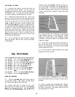
This photo is not 100% accurate Some components
may vary
D D 4 Insert the rear ends of the ribs into the
notches in the TE, then block up the TE with the 1/4"
balsa TE Jig supplied NOTE: THE NARROW END
OF THE TE JIG IS AT RIB W-13. Securely pin the jig
to the building surface, with the aft edge of the Jig even
D D 5 Pin the TE to the TE Jig, making sure the ribs
line up with the plan
D D 6 Glue ribs W-2 through W-13 to the TE
(Apply glue sparingly, to avoid gluing the TE to the
Jig) Glue ribs W-2, W-6 and W-13 to the spar,
making sure they are lined up with the plan, and
positioned at 90-degrees to the work surface
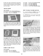
D D 7 Work the notched leading edge onto the
front ends of the ribs NOTE: Position the LE as
shown here
Center LE Vertically On Front Of Ribs
15

