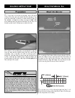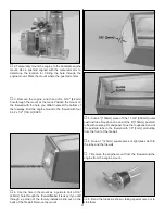
horns. Mount the control horn using 2-56 x 3/8" [9.5mm]
machine screws and the nylon backing plate on the bottoms
of the ruddervators. Note: Turning a 2-56 tap through the
back plate holes makes it easier to get the screws to thread
into the back plate.
❏
7. If you removed the V-tail from the fuse, reinstall it.
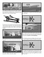
Thread a clevis 15 full turns onto two of the 17-1/2" [445mm]
pushrods.
❏
8. Trim the covering from the pushrod tube exits that are
in front of the V-tail on top of the fuse.
❏
9. Slide the 17-1/2" [445mm] pushrods into the guide
tubes in the fuse. Connect the clevises to the outer hole on
the control horns. With the elevators centered, mark the
pushrods where they cross the V-tail joint.
❏
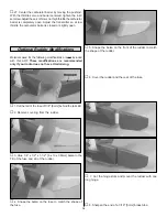
10. Remove the pushrods. Make another mark 1-1/2"
[38mm] in front of the first. At the forward mark make a slight
bend. Reinstall the pushrods and attach the clevises. Note:
This bend is to make the pushrod move as freely as
possible in the pushrod tube. It may take several small
adjustments to get friction-free movement. It is worth the
effort, so take your time until there is no friction.
The engine mounting holes in the firewall fit both the
included universal aluminum engine mount and the
engine mount that comes with the Nelson .40 Quickee
500 engine.
The included engine mount will fit most .25 – .46 size engines.
The bolt pattern of the mount is that of the Nelson .40. This
is to make it easy to upgrade to the Nelson, or experiment
from engine to engine.
❏
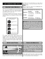
1. Remove the bolts from the engine backplate. Test fit
the mount to the engine. If necessary, file the mount to
accommodate the needle valve (required if using the O.S.
®
.46 FX), or relocate the remote needle to the engine
mounting lug (required for the O.S. .40 LA), as shown in the
photographs.
Mount the Engine
FINAL ASSEMBLY
10

