background image

Read and abide by the following Academy of Model
Aeronautics Official Safety Code:

GENERAL
1. I will not fly my model aircraft in sanctioned events, air
shows, or model flying demonstrations until it has been
proven to be airworthy by having been previously
successfully flight tested.

2. I will not fly my model aircraft higher than approximately
400 feet within 3 miles of an airport without notifying the
airport operator. I will give right of way to, and avoid flying in
the proximity of full-scale aircraft. Where necessary an
observer shall be used to supervise flying to avoid having
models fly in the proximity of full-scale aircraft.

3. Where established, I will abide by the safety rules for the
flying site I use, and I will not willfully and deliberately fly my
models in a careless, reckless and/or dangerous manner.

7. I will not fly my model unless it is identified with my name
and address or AMA number, on or in the model.

9. I will not operate models with pyrotechnics (any device
that explodes, burns, or propels a projectile of any kind).

RADIO CONTROL
1. I will have completed a successful radio equipment ground
check before the first flight of a new or repaired model.

2. I will not fly my model aircraft in the presence of
spectators until I become a qualified flier, unless assisted by
an experienced helper.

3. I will perform my initial turn after takeoff away from the pit
or spectator areas, and I will not thereafter fly over pit or
spectator areas, unless beyond my control.

4. I will operate my model using only radio control
frequencies currently allowed by the Federal Communications
Commission.

❏ 

1.

Fuelproof all areas exposed to fuel or exhaust
residue such as the tank compartment and
underside of hatch, wing saddle area, etc.

❏ 

2.

Check the C.G. according to the measurements
provided in the manual.

❏ 

3.

Be certain the battery and receiver are securely
mounted in the fuse. Simply stuffing them into place
with foam rubber is not sufficient.

❏ 

4.

Extend your receiver antenna and make sure it has
a strain relief inside the fuselage to keep tension off
the solder joint inside the receiver and hasn’t been
cut, shortened or otherwise damaged.

❏ 

5.

Balance your model 

laterally as explained in the

instructions.

❏ 

6.

Use thread-locking compound to secure critical
fasteners such as the set screws that hold the
wheel axles, screws that hold the carburetor arm (if
applicable), screw-lock pushrod connectors, etc.

❏ 

7.

Add a drop of oil to the axles so the wheels will
turn freely.

❏ 

8.

Make sure all hinges are securely glued in place.

❏ 

9.

Reinforce holes for wood screws with thin CA where
appropriate (servo mounting screws, cowl mounting
screws, etc.).

❏ 

10. Confirm that all controls operate in the correct

direction and the throws are set up according to
the manual.

❏ 

11. Make sure there are silicone retainers on all the

clevises and that all servo arms are secured to the
servos with the screws included with your radio.

❏ 

12. Secure connections between servo wires and

Y-connectors or servo extensions, and the
connection between your battery pack and the
on/off switch with vinyl tape, heat shrink tubing or
special clips suitable for that purpose.

❏ 

13. Make sure any servo extension cords you may have

used do not interfere with other systems (servo
arms, pushrods, etc.).

❏ 

14. Secure the pressure tap (if used) to the muffler with

high temp RTV silicone, thread-locking compound
or J.B. Weld.

❏ 

15. Make sure the fuel lines are connected and are

not kinked.

❏ 

16. Balance your propeller (and spare propellers).

❏ 

17. Tighten the propeller nut and spinner.

❏ 

18. Place your name, address, AMA number and

telephone number on or inside your model.

❏ 

19. Cycle your receiver battery pack (if necessary) and

make sure it is fully charged.

❏ 

20. If you wish to photograph your model, do so before

your first flight.

❏ 

21. Range check your radio when you get to the flying field.

During the last few moments of preparation your mind
may be elsewhere anticipating the excitement of the first
flight. Because of this, you may be more likely to overlook
certain checks and procedures that should be performed
before the model is flown. To help avoid this, a check list
is provided to make sure these important areas are not
overlooked. Many are covered in the instruction manual,
so where appropriate, refer to the manual for complete
instructions. Be sure to check the items off as they are
completed (that’s why it’s called a 

check list!).

CHECK LIST

AMA SAFETY CODE (excerpt)

21

Summary of Contents for Viper 500 ARF

Page 1: ...buyer is advised to return this kit immediately in new and unused condition to the place of purchase IMPORTANT NOTE This model is designed for sport flying and AMA Quickie 500 racing We will not quot...

Page 2: ...an fly at reasonable speeds until your confidence and skill are up to their full speed adrenaline rush The Viper 500 ARF is designed for sport flying and AMA Quickie 500 pylon racing competition accor...

Page 3: ...y connection of throttle and aileron servos FUTM3910 Switch Standard with heatshrink to secure to battery Servos 4 3 requiring 35 oz in of torque Servo recommendations The Viper 500 ARF is designed to...

Page 4: ...ecommended that you use only 30 minute or 45 minute epoxy because you will need the working time and or the additional strength Photos and sketches are placed before the step they refer to Frequently...

Page 5: ...lick on Where to Buy If this kit is missing parts contact Great Planes Product Support Replacement Parts List Order Number Description How to Purchase Missing pieces Contact Product Support Instructio...

Page 6: ...mount wing GPMQ3046 4 6 32 x 1 4 Bolts for main landing gear GPMQ3024 5 2 x 3 8 Screws to mount servo tray and hatch GPMQ3820 1 2 Washers to mount servo tray and hatch GPMR3400 1 2 x 9 CA Hinge Strip...

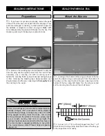
Page 7: ...photo the aileron torque rods protrude from the bottom of the wing cut the covering from the servo opening and the bottom of the four wing bolt holes Turn the wing over and cut the covering from the...

Page 8: ...A to the top and bottom of each hinge Do not use CA accelerator Gently work the aileron up and down while the glue hardens After the CA has fully hardened test the hinges by pulling on the ailerons 1...

Page 9: ...me as you did with the wing Permanently attach the ruddervators to the V tail the using the same hinging technique used with the ailerons 2 Bolt the V tail to the fuse with two 8 32 x 1 1 2 38mm flat...

Page 10: ...make a slight bend Reinstall the pushrods and attach the clevises Note This bend is to make the pushrod move as freely as possible in the pushrod tube It may take several small adjustments to get fri...

Page 11: ...hole in the mount as a guide to drill a 3 16 4 8mm hole through the firewall Note It is okay if you drill through a portion of the factory installed blind nut on the back of the firewall Remove the m...

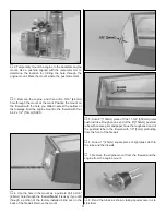
Page 12: ...uselage in the approximate location of the fuel lines from the tank Remove the tank Drill 1 4 6mm holes for the fuel lines Harden the wood around the holes you just drilled with thin CA 12 Guide a 12...

Page 13: ...der Modifications on page 16 1 Trim the servo tray to fit your servos 2 Glue the V tail servo supports to the servo tray The side you glued the supports onto is now the bottom Note If you used servos...

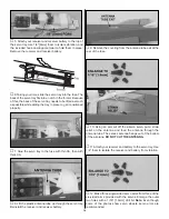
Page 14: ...A 8 Lift the plastic antenna tube up through the servo tray Reinstall the receiver and receiver battery 9 Remove the covering from the antenna tube exit at the rear of the fuse 10 Using an arm cut off...

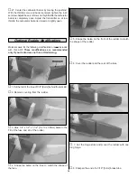
Page 15: ...20 Secure the front of the hatch with a 2 x 3 8 9 5mm screw and 2 washer 21 Determine the size of the throttle servo you are going to use Using the photos as a reference mount the throttle servo in th...

Page 16: ...e modifications are recommended only if your radio does not have V tail mixing 1 Cut the tail of the fuse off 1 4 6mm behind the tail skid 2 Remove covering from the rudder 3 Glue 1 4 x 1 2 x 1 1 2 6...

Page 17: ...dervator pushrod as shown Connect the two ruddervator pushrods together with two 5 32 4mm wheel collars 15 Attach the rudder pushrod to the right hand servo with the Faslink as done with the other ser...

Page 18: ...f the systems in place including the engine landing gear covering and paint and the radio system More than any other factor the C G balance point can have the greatest effect on how a model flies and...

Page 19: ...eight to fall off Use 2 sheet metal screws RTV silicone or epoxy to permanently hold the weight in place 4 IMPORTANT If you found it necessary to add any weight recheck the C G after the weight has be...

Page 20: ...an assistant holding the model using hand signals to show you what is happening If the control surfaces do not respond correctly do not fly Find and correct the problem first Look for loose servo con...

Page 21: ...hasn t been cut shortened or otherwise damaged 5 Balance your model laterally as explained in the instructions 6 Use thread locking compound to secure critical fasteners such as the set screws that h...

Page 22: ...rface flutter Because flutter can quickly destroy components of your airplane any time you detect flutter you must immediately cut the throttle and land the airplane Check all servo grommets for deter...

Page 23: ...to be aware of the relationship between a race model s airspeed and the responsiveness of its flight controls A flight plan greatly reduces the chances of crashing your model just because of poor pla...

Page 24: ...____________ Where Purchased _________________________ Date Construction Started __________________ Date Construction Finished _________________ Finished Weight __________________________ Date of Firs...

Reviews: