28
Cowl and Propeller Installation
The cowl installation shown here is for the DLE-30 gas engine.
Other installations are similar.
❏
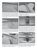
1. Connect the fuel lines to the engine. Connect an
aluminum fuel line plug to the fill/drain line. Drill two 1/4"
[6.4mm] holes at the bottom of the fiberglass sub-cowl and
route the vent line and the fill line through these holes.
❏
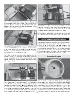
2. Mix up some 6-minute epoxy and thin it down with
denatured alcohol. Brush this onto both sides of the two cowl
rings to fuelproof them.
❏
3. Install the cowl mounting ring to the fuselage using four
4-40 x 1/2" [12.7mm] SHCS, four #4 lock washers, and four
#4 flat washers. Select the bolt holes based on the type of
engine that you are using. For the gas engine, we had to trim
away the standard attachment point and use the alternate
point. A typical glow engine installation should not require
trimming of the cowl rings. Use a drop of thread locking
compound on the screw threads.
❏
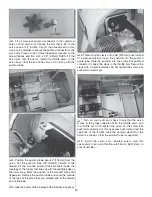
4. Trim the cowl ring to match the mounting ring.
❏
5. Cut pieces of card stock (old cereal boxes work well)
and tape them to the fuselage side so that the trailing edge
of the card stock is taped to the fuselage a few inches back
from the cowl mounting ring. Trace the pattern of the head
and muffler onto the card stock. Trim the card stock away a
little at a time until you are satisfied with how it fits. This will
be transferred to the cowl.
❏
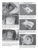
6. Assemble the cowl centering tool as shown. Glue the
four 3mm thick plywood rings together. Then, glue those to
the larger flange ring. Glue the mounting adapter disc to the
top of the assembly.
Note:
The center hole of the mounting
adapter disc is drilled for a 5/16" [7.9mm] crankshaft. Please
use a 13/32" drill or a 10mm drill to enlarge the hole for the
DLE-30 engine.
Summary of Contents for Waco YMF-5
Page 40: ......


