6
PREPARE FOR ASSEMBLY
Before you begin assembling your model, use a covering iron
set to a medium temperature (about 250° F [121° C]) to tack
down any loose or wrinkled covering. Securely tack down the
edges of trim and where seams are present and around the
aileron servo hatch covers. We recommend using a Coverite
™
(COVR2700) covering iron with a sock (COVR2702).
WING ASSEMBLY
Aileron Servo Preparation
❏
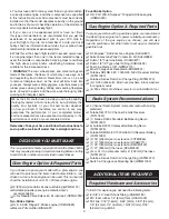
1. Locate the long servo arm that came with your servo.
For Futaba standard servos this is the arm that is already
installed on the servo. For other radio systems, please use
the arm that is at least 5/8" [15.9mm] long from the center
of the shaft to the outermost hole. Center four servos using
your radio. Remove the servo arm screw and reposition the
servo arm on the splined output shaft so that the arm is 90°
(perpendicular) to the servo case side. Clip off the unused
servo arms so that your servos look like those in the photo.
Install the servo arm screw.
❏
2. Use a 5/64" [2mm] drill bit to drill the outermost servo
arm hole on all four aileron servos.
Bottom Wing Assembly
❏ ❏
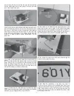
1. Working with the bottom left wing now, cut out three
1/2" x 1" [13mm x 25mm] pieces of thin card stock (not
supplied). You may use construction paper or a manila folder
for this purpose. Lay the servo on a flat surface with the
arm hanging down over the edge of your table. Locate two
19x19x9mm hardwood blocks. Position the blocks under the
servo mounting tabs and place a piece of card stock in the
locations shown. Holding the blocks and servo in position,
use a 1/16" [1.6mm] drill to drill four holes for the servo
mounting screws.
❏ ❏
2. Install the four servo mounting screws that came
with your servo. Remove the screws and harden each of the
Summary of Contents for Waco YMF-5
Page 40: ......


