in the servo arm using thin CA. (Do not glue the clevis to the
servo arm!). Confirm that your servo arm is still perpendicular
to the servo case. Install a 2mm x 4mm sheet metal screw into
the clevis on the elevator control horn and carefully tighten it
down. Cut off the excess pushrod beyond the clevises.
❏
6. Repeat step 5 for the rudder pushrod using the 5/64" x
19" [2mm x 490mm] carbon rod.
❏
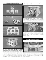
1. Trim the covering from the landing gear slots in
the fuselage.
❏
2. Measure and mark 1-9/16" [40mm] from the front and
1/4" [6mm] from the bottom of the wheel pants. Drill a 1/8"
[3mm] hole at your marks on each side of both wheel pants.
Accuracy during this step will ensure that your wheels are
positioned straight inside the pants. When drilling the hole,
make a pilot hole with a smaller bit first, then enlarge the
hole to the correct diameter.
❏
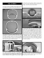
3. Fit the 3mm x 25mm machine screw (axle) through the
hole in the landing gear and through the inside hole in the
pant. Thread a 3mm nut onto the screw followed by a wheel.
Apply a drop of thread-locking compound near the base of
the screw and finish tightening the nut. Thread another nut
onto the screw against the wheel, but still allowing the wheel
to rotate freely on the axle. Secure this nut with thread-
locking compound. The end of the axle screw will pass
through the outside hole in the pant.
❏
4. Attach the landing gear to the fuselage using four 3mm
x 8mm machine screws, four 3mm washers, and thread-
locking compound.
❏
5. Glue the tail skid to the underside of the fuselage 1/4"
[6mm] from the aft end. The longest side of the skid goes
against the fuselage. Be sure to remove the covering from the
fuselage where the skid will be glued before you attach it.
INSTALL THE LANDING GEAR
14


