background image

The Yak 54 EP ARF includes motor mount parts for both the
Great Planes brushless C35-30-950 out-runner motor and
the brushless B24-33-4040 in-runner equipped with the
Great Planes 24mm gear drive. Other motors may be able to
be installed; however, modification to one of the mounting
box firewalls would be necessary to suit the size and mount
pattern of your equipment.

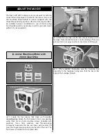
1. Locate the four pieces that make up the motor

mounting box. Attach the front piece to the motor gearbox
using three 3mm x 6mm machine screws (included with
gearbox), three 3mm washers, and thread-locking
compound. Assemble the box as shown with medium CA
glue (the longer side piece being on the left of the box). The
front piece is installed in the forward slots.

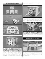
2. Slide the assembly over the box already attached to the

fuselage. Trace around the motor onto the fuselage. This area
will need to be cut away in order for the motor to fit through.

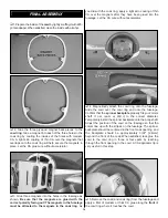
3. When satisfied, thoroughly glue the mounting box

assembly to the fuselage, being sure that the box is flat
against the fuselage firewall.

In-runner Brushless Motor with

24mm Gear Drive

MOUNT THE  MOTOR

15

Summary of Contents for Yak 54 36 ARF

Page 1: ...y Services at the address below Hobby Services 3002 N Apollo Dr Suite 1 Champaign IL 61822 USA Include a letter stating your name return shipping address as much contact information as possible daytim...

Page 2: ...link then select the YAK 54 EP 3D ARF If there is new technical information or changes to this model a tech notice box will appear in the upper left corner of the page We urge you to join the AMA Acad...

Page 3: ...Conversion Short Crystal Low Band FUTL62 High Band FUTL63 2 Futaba C 25 Extension Slim Wire 6 152mm FUTM4506 Futaba 6 152mm Dual Servo Extension J FUTM4130 The YAK 54 EP 3D ARF comes with a mounting...

Page 4: ...ou use only 30 minute or 45 minute epoxy because you will need the working time and or the additional strength Photos and sketches are placed before the step they refer to Frequently you can study pho...

Page 5: ...ch GPMA2953 Decal Sheet GPMA2954 Hardware Set Fuse Fuselage Stab Horizontal Stabilizer Fin Vertical Fin LE Leading Edge TE Trailing Edge LG Landing Gear Ply Plywood Inches mm Millimeters ESC Electroni...

Page 6: ...t names exactly as they are written in the Kit Contents list Great Planes Product Support 3002 N Apollo Drive Suite 1 Champaign IL 61822 Telephone 217 398 8970 ext 5 Fax 217 398 7721 E mail airsupport...

Page 7: ...nd ailerons Test fit the pre cut CA hinges into the slots If any are difficult to install enlarge the slots with your knife 2 Insert the CA hinges halfway into the slots in the wing panels Push small...

Page 8: ...vo splines facing the LE of the wings After the glue has cured confirm that the servos are properly secured to the wings and reinforce with extra glue if necessary 7 Locate two double sided servo arms...

Page 9: ...of the control horn to adjust the length of the pushrods as needed Remove the servo arms from the aileron servos Connect the other adjustable clevises on the aileron pushrods to the control horns and...

Page 10: ...clamps to hold the spar doublers in place while the epoxy cures 1 Fit the vertical fin into place and use a felt tip pen to trace around the fin where it meets the fuse Remove the fin from the fuse a...

Page 11: ...tor halves 6 Lay the elevators on your work surface and confirm that they both lay flat If not tweak or bend the elevator joiner wire slightly until they do Do not glue the joiner wire in place at thi...

Page 12: ...onto the ends of the elevator joiner wire Install the elevators onto the joiner wire while fitting the CA hinges into their mating slots in the horizontal stabilizer As you did with the ailerons use...

Page 13: ...nto the servo spline perpendicular to the servo case remove it from the servo and rotate it 180 Decide which way fits best closest to perpendicular and cut off the arm that isn t used Attach an adjust...

Page 14: ...th a smaller bit first then enlarge the hole to the correct diameter 3 Fit the 3mm x 25mm machine screw axle through the hole in the landing gear and through the inside hole in the pant Thread a 3mm n...

Page 15: ...the motor gearbox using three 3mm x 6mm machine screws included with gearbox three 3mm washers and thread locking compound Assemble the box as shown with medium CA glue the longer side piece being on...

Page 16: ...box The front piece is installed in the aft slots 2 Attach the aluminum adapter to the back of the out runner using the screws supplied with the motor Attach the motor to the mounting box with four 3...

Page 17: ...na through the inside of the fuselage to the back The antenna exits from a small hole drilled in the location shown 5 Make a battery strap out of the supplied hook and loop material 8 200mm long by ov...

Page 18: ...hatch that continues the shape of the lightening hole arc across the webbing Glue the battery hatch retainer to the back former as shown at the line you drew 9 Trim the covering between the spars at...

Page 19: ...hey have been glued into the fuselage Let the CA cure without accelerator 4 Magnetically attach the cowl ring onto the fuselage Slide the cowl over the cowl ring and onto the fuselage Confirm that the...

Page 20: ...servo arms from the servos and reposition them so they are centered Reinstall the screws that hold on the servo arms 2 With the transmitter and receiver still on check all the control surfaces to see...

Page 21: ...ing the C G up to 1 2 13mm forward or 1 2 13mm back to change the flying characteristics Moving the C G forward may improve the smoothness and stability but the model may then require more speed for t...

Page 22: ...ded wires on old servo connectors poor solder joints in your battery pack or a defective cell or a damaged receiver crystal from a previous crash Get help from an experienced pilot when learning to op...

Page 23: ...ne is prohibited 4 I will operate my model using only radio control frequencies currently allowed by the Federal Communications Commission 5 I will not knowingly operate my model within three miles of...

Page 24: ...airspeed by keeping the nose down as you turn onto the crosswind leg Make your final turn toward the runway into the wind keeping the nose down to maintain airspeed and control Level the attitude whe...

Page 25: ...odel around A lot of models will require a little bit of rudder correction usually right rudder during this maneuver Some planes will require a little aileron correction to keep the wings level as wel...

Page 26: ...here are a lot of small corrections made to keep most planes in the maneuver This is one maneuver where less control is needed Too much elevator and the model goes into an uncontrollable stall The C G...

Page 27: ...Have a ball But always stay in control and fly in a safe manner GOOD LUCK AND GREAT FLYING Make a copy of this identification tag and put it on or inside your model 27...

Page 28: ...____________ Where Purchased _________________________ Date Construction Started __________________ Date Construction Finished _________________ Finished Weight __________________________ Date of Firs...

Reviews: