17
o
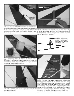
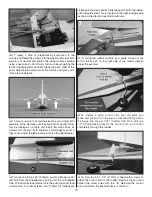
13 . Align the tip of the rudder with the tip of the vertical
stab . Deflect the rudder both directions a few times while
pushing the rudder forward into the TE of the vertical stab .
Remove the T-pins and apply five drops of thin CA to both
sides of each hinge . Clean up any mess with CA debonder
and allow the CA to cure .
Servo, Pushrod & Control
Horn Installation
o
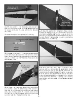
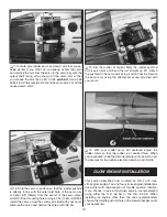
1 . Remove the wings and support the model using your
building stand . Measure 7/16" [11mm] from the inboard edge
of each elevator and make a mark using a felt-tip pen .
o
2 . Locate two nylon control horns . Center a horn directly
over the mark you made, being careful to position the clevis
holes directly above the hinge line . Hold the horn in this
position and drill two 3/8" [9 .5mm] deep holes using a 1/16"
[1 .6mm] drill . Be careful not to drill through the elevator
completely . Do this for both elevators .
o
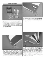
3 . Use four #2 x 3/8" [9 .5mm] sheet-metal screws to install
the elevator control horns . Remove the horns and carefully
wick one drop of thin CA into the screw holes . Allow the CA
to cure and then reinstall the horns .
o
4 . Locate two 2-56 x 36" [914mm] one-end threaded
pushrods . Slide a silicone clevis retainer onto each pushrod
and thread a nylon clevis on so that at least 1/16" [1 .6mm] of
thread protrudes past the clevis barrel .
o
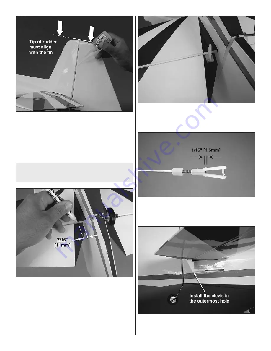
5 . Insert the pushrods into the fuselage through the upper
pushrod guide tubes at the aft fuselage and connect them to
the outermost hole of each elevator control horn .
Summary of Contents for Z-526 ZLIN krobat
Page 40: ......


