


6
ABOUT THE CLEANER AND ACCESSORIES:
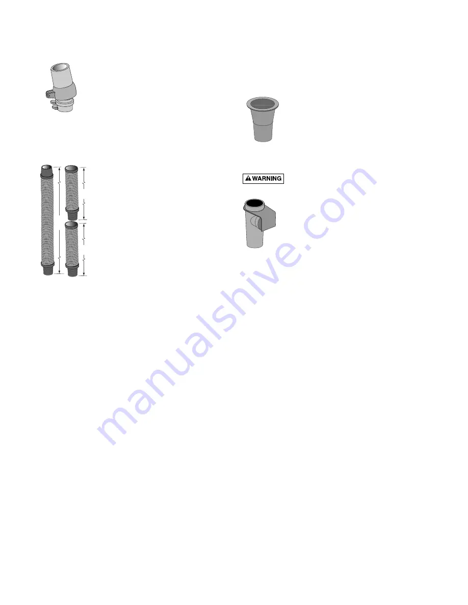
Swivel assembly (Figure 9)
Installing the swivel assembly is a snap.
Just insert it into the cleaner body and
give it a quarter turn.
If you attach a unidapt handle to the
swivel for manual vacuuming, be sure it
is the special, floating unidapt handle
provided with the cleaner (Replacement
Part No. GW9019). Use of a different
unidapt handle will hinder the cleaner’s performance.
Hoses (24’ and two 8’ lengths – Figure 10)
The unit includes a 24’ hose and two 8’
extensions. Do not cut any of these
hoses.
The best hose length is at least 4’
longer than the distance from your
suction source (whether skimmer or
dedicated suction line) to the furthest
point in the pool. If the hose seems to
be too long, remove the 8’ section pro-
vided. Do not cut the 24’ hose.
Be sure to connect the tapered end of
the 24’ hose (marked “connect to clean-
er”) to the cleaner head.
If additional hose is needed, use only
the specially designed 8’ extension hose from your Sta-
Rite dealer (order replacement part No. GW9511). Use
of another manufacturer’s hose will hinder cleaner cov-
erage (this also holds true for the 24’ hose). If you need
to replace the 24’ hose, buy only the original equipment
hose (order replacement part No. GW9525).
Hose
( 6” connector ) female x female (purchase acces-
sory No. GW9021) If required, this will accommodate a
male x male connection at the skimmer.
Reducer cone (Figure 11)
The reducer cone is required to make
most hose connections. When used, it
will keep the hose in place if the filter
system is stopped.
Automatic vacuum regulator (Figure 12)
Hazardous suction. Can cause entrap-
ment with severe personal injury or drowning.
Vacuum regulator should be installed in all
situations. If the cleaner moves very slowly
or not at all (indicating low vacuum in the
system), see Troubleshooting Chart, Page 7.
The regulator includes two black rubber
regulator caps. One is installed on the regu-
lator at the factory, and one is in the acces-
sory bag. The cap marked “50” in the acces-
sory bag is for systems with extremely high vacuum.
Use of this cap will help prevent the cleaner from
“walking” out of the pool.
Make sure the vacuum regulator, especially the black
rubber cap, is submerged at all times. If not, the pump
will suck air through the regulator and lose prime. This
could damage the pump.
1883 0795
24'
8'
8'
Figure 9
Figure 10
Figure 11
Figure 12
ABOUT BUMPER INSERTS
Bumper Inserts (see Key 2A, Page 10) help to make the
cleaner more buoyant to allow better access to the
shallow end of the pool. Do not install inserts from the
top; they will become jammed and not work properly.
Only install inserts from the bottom.
If the bumper on the cleaner appears to lift the cleaner
to the surface of the pool, check for trapped air in the
cleaner and hose. If no air is found, remove one
bumper insert block and watch and see if the cleaner
remains submerged and on the pool floor while work-
ing. If not, remove individual insert blocks as needed
until the cleaner rests on the pool floor and operates
properly.


