background image

8

If you have any questions, please call 1-800-752-0183

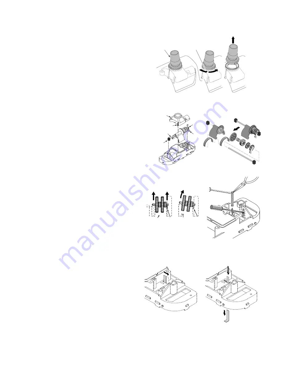
1. Remove swivel assembly (Figure 13) from the top of

the cleaner by turning it 1/4-turn counterclockwise
and pulling straight up on  it.

2. Turn cleaner upside down. Remove 4 screws and

remove lower body assembly from shroud.

3 . Turn lower body assembly right side up. Unsnap the

2 clips on the oscillator chamber cap (Figure 14A); lift
it off.

4. Pull the long gear shaft straight up (Figure 14A) by

the blocks on the ends of the shaft. Hold the seals in
the oscillator and the blocks on the shaft. The cam
may interfere with the shaft mounting post; if so, turn
it slightly on the shaft until it clears the post. The shaft
assembly can now be disassembled (Figure 14B).

5. Slide the long gear shaft out of the oscillator (with

gears, complete); make sure that you don’t lose the
seals out of the oscillator which may fall out at this
point (Figure 14B).

5A. Oscillator seals are replaceable.

5B. Ratchet gear set and long shaft are replaceable as a

unit.

6. Remove the short gear shaft and gears (Figure 15); do

not lose the gears off of the shaft.

NOTE:

Put one finger under the gear nearest the end

of the cleaner and lift straight up to remove the short
gear shaft. Do not twist or bend the shaft.

7. With a small screwdriver (such as a jeweler’s screw-

driver), a pencil, or a pen point, depress and remove
the coil spring from the  movable brush mounting
post (Figure 16). Replace the brush and the spring if
necessary.

8. The metal ratchet tab slides out of its slot sideways;

replace it by removing the center brushes and sliding
in a new ratchet tab until it is flush with the edge of
plastic holder (Figures 17 and 18). Replace the center
brushes.

9. The brush ring pops out of the cleaner body for easy

replacement.

10. If you need to replace the bumper, turn the shroud

and bumber assembly upside down and remove the
two screws holding the bumper to the shroud.

1889 0795

Clip

Ocillator
Chamber
Cap

Block

Long Gear Shaft

Block

Cam

Locked

Twist CCW
1/4 Turn

Pull Straight
Up

"Click" at
this point

Swivel
assembly

3337 1098

This –

Not This 

Lift here –

Pin

not here

Pin

3327 1098

}

}

1887 0795

1886 0795

1. Slide metal ratchet tab 
toward end of cleaner body

1885 0795

2. Slide metal ratchet tab
    down through cleaner body

1884 0795

Figure 14A

Figure 14B

Figure 13

Figure 15

Figure 16

Figure 17

Figure 18

ABOUT DISASSEMBLY

Summary of Contents for GW9500

Page 1: ...uga Ont Murrieta CA ABOUT SAFETY Before installing the cleaner review and understand all warnings and safety information on inside cover of manual ABOUT INSTALLATION Please use the convenient water re...

Page 2: ...s or to work under a solar cover It was also not designed to do initial cleanup for a new pool or when opening your pool for the season Suction entrapment injury and drown ing hazard If your pool has...

Page 3: ...for vacuuming Figure 4 Decide on the vacuum connection you are going to use either a skimmer or a dedicated wall fitting and adjust the pump valves if your system has valves to direct all vacuum ther...

Page 4: ...r system unless pool cleaner will not operate with regulator installed Note Each pool s hydraulic system and vacuum con nections are different Be sure you have installed the white plastic vacuum regul...

Page 5: ...e of air To eliminate this slightly open the main drain valve to supplement the water intake The cleaner may slow down a bit when you change the suction Skimmer connection Some pool owners remove the...

Page 6: ...ne is required to make most hose connections When used it will keep the hose in place if the filter system is stopped Automatic vacuum regulator Figure 12 Hazardous suction Can cause entrap ment with...

Page 7: ...running and submerged If the turning brush does not move to the down position within 2 minutes call Customer Service at 1 800 752 0183 4 The cleaner was not designed to work under solar covers If you...

Page 8: ...f the shaft NOTE Put one finger under the gear nearest the end of the cleaner and lift straight up to remove the short gear shaft Do not twist or bend the shaft 7 With a small screwdriver such as a je...

Page 9: ...r cap and clip it in place 6 Install the rubber vacuum skirt on the cleaner with the word OUTSIDE showing Start at the large pin on the back of the cleaner head see Figure 22 and work around the clean...

Page 10: ...b Stainless Steel GW9523 17 Oscillator Seal Kit Incl 2 Seals GW9004 18 Oscillator Assembly Kit Incl Key 17 GW9503 Ratchet Ass y not sold separately 19 Center Brush Kit Set of 2 GW9013 24 Vacuum Hose G...

Page 11: ...hose connected to the cleaner body or with the hose coiled To do so will cause the hose to take a set or kink over a period of time When reinstalled in the pool the hose will tend to stay coiled and...

Page 12: ...r replace the defective product at its sole discre tion Purchasers must pay all labor and shipping charges necessary to replace the product covered by this warranty Requests for warranty service must...

Reviews: