background image

9

ABOUT ASSEMBLY

If you have any questions, please call 1-800-752-0183

1. Put both white seals in the oscillator; hold them in

place. 

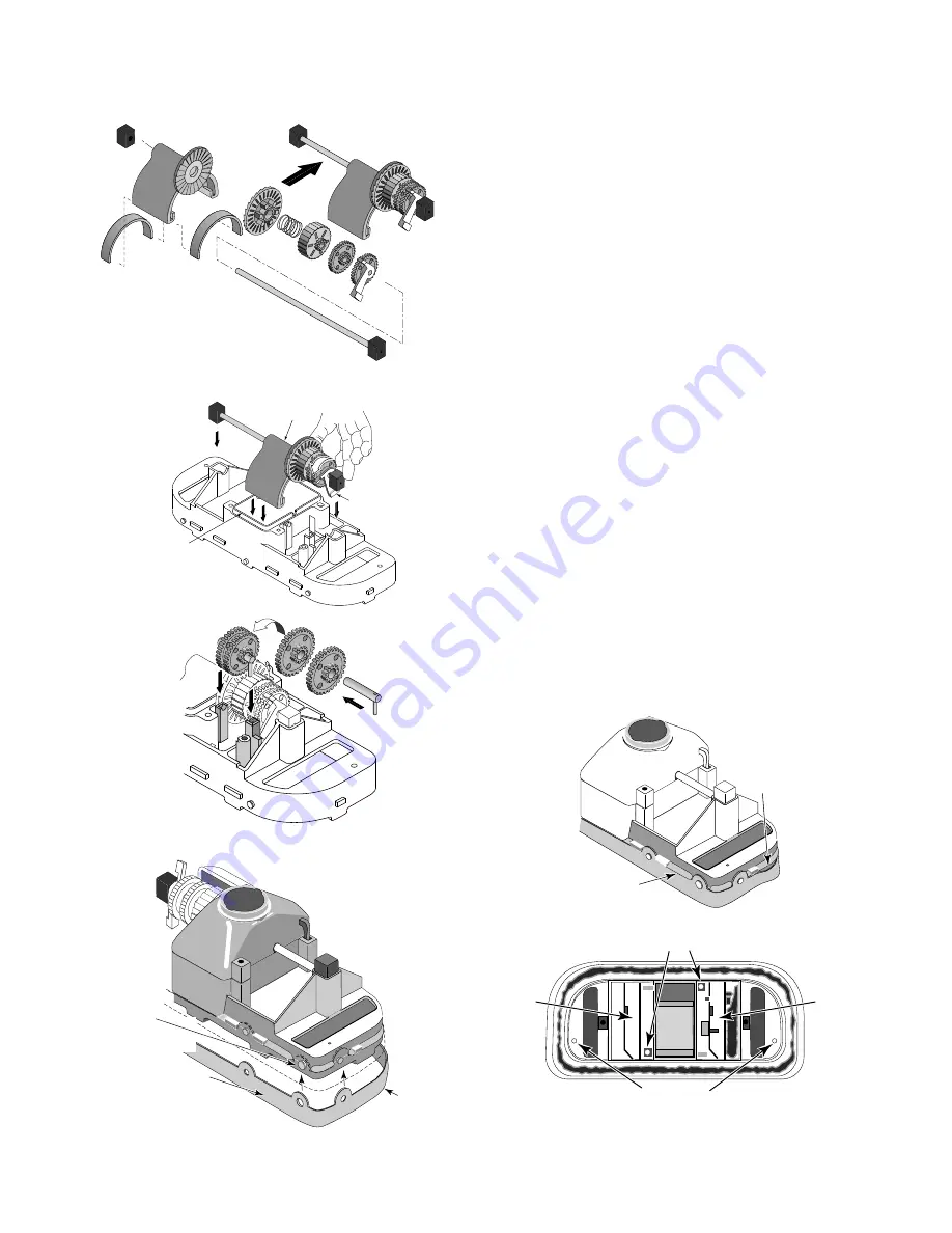
2. Install the oscillator on the long gear shaft. Install the

ratchet gear on the shaft so that the teeth engage the
ratchet on the oscillator. Install the spring, ratchet
drum, pinion gear (large gear first), and cam (gear end
first) on the shaft (See Figure 19). Hold the gears on the
shaft while installing them, and compress the clutch
spring to allow assembly to slip into place between the
posts (See Figure 19).

3. Install the long gear shaft and end blocks in the clean-

ing head with the large arm of the cam down (see
Figure 20).

4. Reinstall the short gear shaft and two gears (See Figure

21); the small pinion gears and the shaft pin go on the
side toward the end of the cleaner – away from the
oscillator box. Make sure that the gears engage the
gears on the long gear shaft.

5. Install the oscillator chamber cap and clip it in place.
6. Install the rubber vacuum skirt on the cleaner with the

word  ‘OUTSIDE’ showing. Start at the large pin on the
back of the cleaner head (see Figure 22) and work
around the cleaner. Make sure the skirt is flush against
the stop strips on the cleaner head (see Figure 23).

7. Turn the cleaner over. If you removed the bumper and

brush ring, replace them now.

8. Install the lower body assembly in the shroud. Fasten

the cleaning head in place with 4 screws (2 long, 2 short
– see Figure 24).
NOTE:

Make sure that you do not dislodge the rubber

vac skirt while inserting the lower body assembly past
the brush ring.

1894 0795

Figure 19

Swing Cam
Arm up for
Clearance

Make sure Oscillator
is partially inserted in
chamber while reinstalling
Shaft Assembly

Oscillator
Chamber

Figure 20

Figure 21

Start here with 
large button when
installing vacuum skirt.

OU

TSID

E

'Outside' will show
(facing out) when 
skirt is correctly installed.

Rubber
vacuum skirt

1893 0795

Figure 22

This

Not
This

1892 0795

Figure 23

#10-16x1" Screws

#10-16x1-3/4" Screws

Center
Brush
Location

Center
Brush
Location

Bottom View of Cleaner

1891 0795

Figure 24

Summary of Contents for GW9500

Page 1: ...uga Ont Murrieta CA ABOUT SAFETY Before installing the cleaner review and understand all warnings and safety information on inside cover of manual ABOUT INSTALLATION Please use the convenient water re...

Page 2: ...s or to work under a solar cover It was also not designed to do initial cleanup for a new pool or when opening your pool for the season Suction entrapment injury and drown ing hazard If your pool has...

Page 3: ...for vacuuming Figure 4 Decide on the vacuum connection you are going to use either a skimmer or a dedicated wall fitting and adjust the pump valves if your system has valves to direct all vacuum ther...

Page 4: ...r system unless pool cleaner will not operate with regulator installed Note Each pool s hydraulic system and vacuum con nections are different Be sure you have installed the white plastic vacuum regul...

Page 5: ...e of air To eliminate this slightly open the main drain valve to supplement the water intake The cleaner may slow down a bit when you change the suction Skimmer connection Some pool owners remove the...

Page 6: ...ne is required to make most hose connections When used it will keep the hose in place if the filter system is stopped Automatic vacuum regulator Figure 12 Hazardous suction Can cause entrap ment with...

Page 7: ...running and submerged If the turning brush does not move to the down position within 2 minutes call Customer Service at 1 800 752 0183 4 The cleaner was not designed to work under solar covers If you...

Page 8: ...f the shaft NOTE Put one finger under the gear nearest the end of the cleaner and lift straight up to remove the short gear shaft Do not twist or bend the shaft 7 With a small screwdriver such as a je...

Page 9: ...r cap and clip it in place 6 Install the rubber vacuum skirt on the cleaner with the word OUTSIDE showing Start at the large pin on the back of the cleaner head see Figure 22 and work around the clean...

Page 10: ...b Stainless Steel GW9523 17 Oscillator Seal Kit Incl 2 Seals GW9004 18 Oscillator Assembly Kit Incl Key 17 GW9503 Ratchet Ass y not sold separately 19 Center Brush Kit Set of 2 GW9013 24 Vacuum Hose G...

Page 11: ...hose connected to the cleaner body or with the hose coiled To do so will cause the hose to take a set or kink over a period of time When reinstalled in the pool the hose will tend to stay coiled and...

Page 12: ...r replace the defective product at its sole discre tion Purchasers must pay all labor and shipping charges necessary to replace the product covered by this warranty Requests for warranty service must...

Reviews: