Air-to-water Heat Pump
10
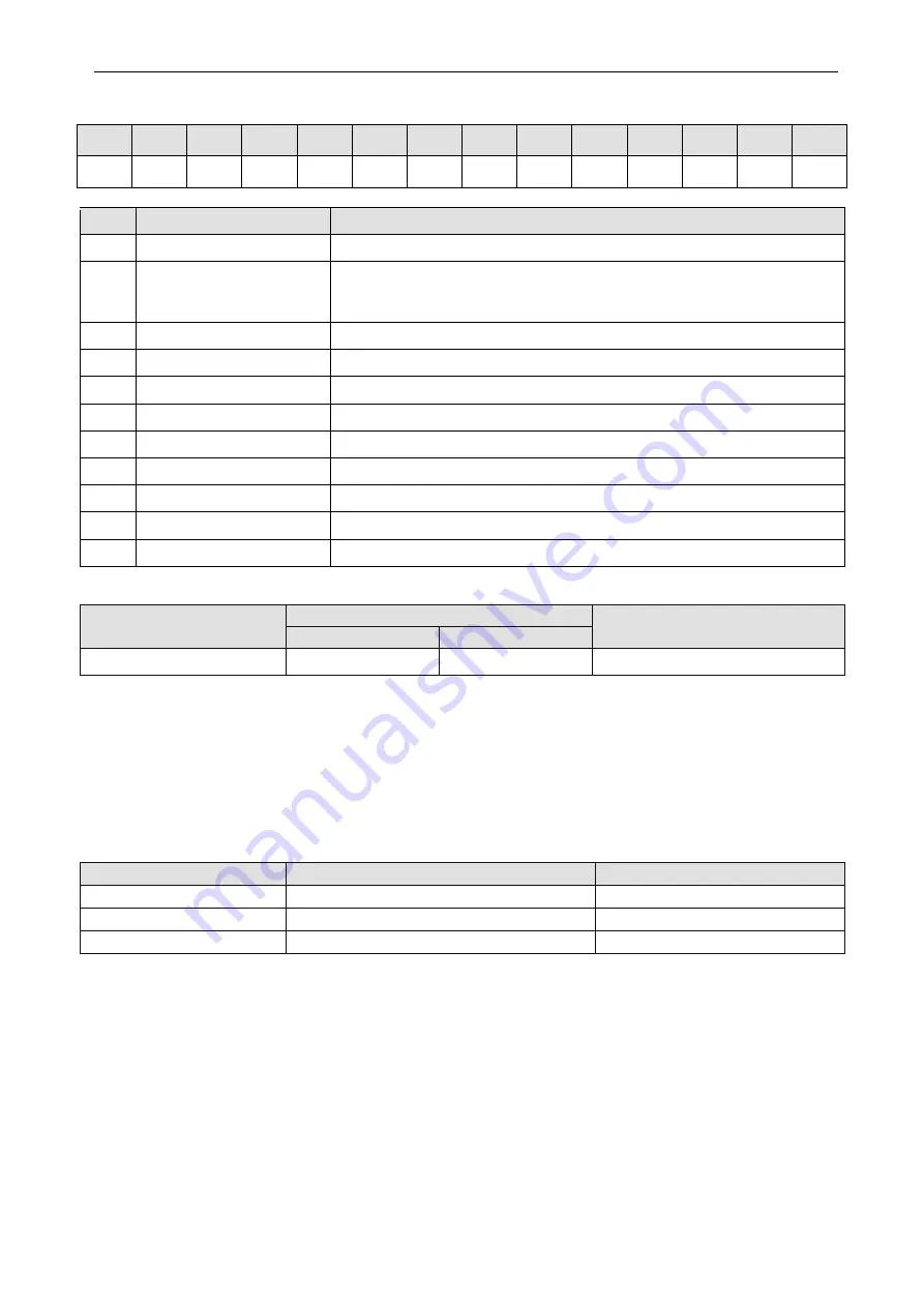
4 Nomenclature
GRS
-
/
-
1
2
3
4
5
6
7
8
9
10
11
SN
Description
Options
1
Product code
GRS—Heat pump water heater
2
Heating method
D—Direct heating; C—Circulating heating; S—Static heating;
Dm-Direct heating modular;
Cm- Circulating modular
3
Functions
Q—Multifunctional; Null for single function
4
Heating capacity code
Nominal heating capacity(Unit:kW)
5
Inverter system
Pd—DC inverter; Null for fixed speed
6
type of heat pump
Re
—
Low-temperature heat pump; Null for Normal-temperature heat pump
7
Water tank mode
E—100L;F—150L;G—200L;H—250L;Null in case of no water tank
8
Climate condition
Null for T1;T2-Low temp;T3-High temp
9
Refrigerant
R22—Default;R407c—N;R410A—Na;R134a—Nb;R32
—
Nh;R417A—Ne
10
Design number
A,B,C…or A1,A2…,B1,B2…
11
Power supply
Refer to QJ/GD23.00.004
Model Line-Up
Model Name
Capacity
Power supply
Heating1, kW
Heating2, kW
GRS-Cm18PdRe/NhA-M
18.1
16.1
380-415V 3N~ 50Hz
NOTES:
(1) 1Capacities and power inputs are based on the following conditions:
Indoor Water Temperature 30°C/35°C, Outdoor Air Temperature 7°C DB/6°C WB
(2) 2Capacities and power inputs are based on the following conditions:
Indoor Water Temperature 23°C/18°C, Outdoor Air Temperature 35°C DB/24°C WB
Operation
Range
Mode
Heat Source Side Temperature (°C)
User Side Temperature (°C)
Hot water
-30~45
30~55
Heating
-30~35
25~60
Cooling
-10~48
5~25
5 Installation Example
CASE 1: Connecting Under-floor Coil for Heating and Cooling
NOTES:
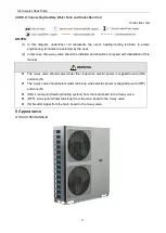
(1) In this diagram, under-floor coil represents the user’s heating/cooling terminal. In actual
engineering, terminals are selected by the user.
(2) By pass valve must be installed to secure enough water flow rate, and by pass valve should be
installed at the collector.


