background image

Air-to-water Heat Pump 

28 

The recovery equipment shall be in good working order with a set of instructions concerning the 

equipment that is at hand and shall be suitable for the recovery of flammable refrigerants. 

In addition, a set of calibrated weighing scales shall be available and in good working order. 
Hoses shall be complete with leak-free disconnect couplings and in good condition. Before using 

the recovery machine, check that it is in satisfactory working order, has been properly maintained and 
that any associated electrical components are sealed to prevent ignition in the event of a refrigerant 
release. Consult manufacturer if in doubt. 

The recovered refrigerant shall be returned to the refrigerant supplier in the correct recovery cylinder, 

and the relevant Waste Transfer Note arranged. Do not mix refrigerants in recovery units and especially 
not in cylinders. 

If compressors or compressor oils are to be removed, ensure that they have been evacuated to an 

acceptable level to make certain that flammable refrigerant does not remain within the lubricant. The 
evacuation process shall be carried out prior to returning the compressor to the suppliers. Only electric 
heating to the compressor body shall be employed to accelerate this process. When oil is drained from a 
system, it shall be carried out safely. 

13.2 Decommissioning 

Before carrying out this procedure, it is essential that the technician is completely familiar with the 

equipment and all its detail. It is recommended good practice that all refrigerants are recovered safely. 
Prior to the task being carried out, an oil and refrigerant sample  shall be taken in case analysis is 
required prior to re-use of reclaimed refrigerant. It is essential that electrical power is available before the 
task is commenced. 

(1) Become familiar with the equipment and its operation.
(2) Isolate system electrically.
(3) Before attempting the procedure ensure that: mechanical handling equipment is available, if

required, for handling refrigerant cylinders; all personal protective equipment is available and
being used correctly; the recovery process is supervised at all times by a competent person;
recovery equipment and cylinders conform to the appropriate standards.

(4) Pump down refrigerant system, if possible.
(5) If a vacuum is not possible, make a manifold so that refrigerant can be removed from various

parts of the system.

(6) Make sure that cylinder is situated on the scales before recovery takes place.
(7) Start the recovery machine and operate in accordance with manufacturer's instructions.
(8) Do not overfill cylinders. (No more than 80 % volume liquid  charge).
(9) Do not exceed the maximum working pressure of the cylinder, even  temporarily.
(10) When the cylinders have been filled correctly and the process completed, make sure that the

cylinders and the equipment are removed from site promptly and all isolation valves on the
equipment are closed off.

(11) Recovered refrigerant shall not be charged into another refrigeration system unless it has been

cleaned and checked.

Summary of Contents for GRS-Cm18PdRe/NhA-M

Page 1: ...Owner s Manual Original Instructions Air to water Heat Pump Model GRS Cm18PdRe NhA M ...

Page 2: ...nd inspection which may impact the normal operation of unit please do not disassemble the unit by yourself You can contact with the special maintenance center of our company if necessary 3 For personal injury or property loss and damage caused by improper operation such as improper installation and debugging unnecessary maintenance violation of related national laws and rules and industrial standa...

Page 3: ... Charging and Discharging of Refrigerant 15 10 Installation of Insulated Water Tank 17 10 1 Selection of Water Pipe 17 10 2 Model Selection of Water Pump 18 10 3 Installation measure 19 10 4 Connection of waterway system 20 10 5 Requirements on water quality 21 10 6 Electric wiring work 21 11 Wring Diagram 22 11 1 Control Board 22 11 2 Electric Wiring 23 12 Commissioning 24 12 1 Check before start...

Page 4: ... of the unit for longer life and reliable operation If the supply cord is damaged it must be replaced by the manufacturer its service agent or similarly qualified persons in order to avoid a hazard The appliance shall be installed in accordance with national wiring regulations This product is a kind of comfort air conditioning and is not allowed to be installed where there are corrosive explosive ...

Page 5: ...revent fire Do not use octopus multipurpose plug or mobile terminal board for wire connection Be sure to pull out the power plug and drain the unit and water tank when unit is not in use for a long time Otherwise the accumulated dust may cause overheating fire or freeze of water tank or heater exchanger in winter Never damage the electric wire or use the one which is not specified Otherwise it may...

Page 6: ...by yourself Improper repair may cause electric shock or fire so you should contact the service center to repair Don t step on the top of the unit or place anything on it There is the danger of fall of things or people Never block the air inlet and outlet of unit It may reduce efficiency or cause stop of the unit and even fire Keep pressurized spray gas holder and so on away from the unit above 1m ...

Page 7: ...ldren aged from 8 years and above and persons with reduced physical sensory or mental capabilities or lack of experience and knowledge if they have been given supervision or instruction concerning use of the appliance in a safe way and understand the hazards involved Children shall not play with the appliance Cleaning and user maintenance shall not be made by children without supervision The appli...

Page 8: ... to prevent the water tank pipe line and water pump from frost cracking Never press the button with sharp objects to protect manual controller Never use other wires instead of special communication line of the unit to protect control elements Never clean the manual controller with benzene thinner or chemical cloth to avoid fading of surface and failure of elements Clean the unit with the cloth soa...

Page 9: ...guisher adjacent to the charging area Where electrical components are being changed they shall be fit for the purpose and to the correct specification At all times the manufacturer s maintenance and service guidelines shall be followed If in doubt consult the manufacturer s technical department for assistance The following checks shall be applied to installations using flammable refrigerants The c...

Page 10: ...aratus is mounted securely Ensure that seals or sealing materials have not degraded such that they no longer serve the purpose of preventing the ingress of flammable atmospheres Replacement parts shall be in accordance with the manufacturer s specifications NOTE The use of silicon sealant may inhibit the effectiveness of some types of leak detection equipment Intrinsically safe components do not h...

Page 11: ...Air to water Heat Pump 8 2 Diagram of the Operating Principle NOTE In actual engineering terminals heating cooling device are selected by the user ...

Page 12: ...is heated circularly to reach the set value of leaving water temperature and meet the user s heating demand Cooling In cooling mode through refrigeration circulation the unit absorbs heat from the cool water in the water side heat exchanger and releases the heat to the low grade energy high temperature heat source in the surrounding environment By controlling the engineering water valve the water ...

Page 13: ...2 B1 B2 11 Power supply Refer to QJ GD23 00 004 Model Line Up Model Name Capacity Power supply Heating1 kW Heating2 kW GRS Cm18PdRe NhA M 18 1 16 1 380 415V 3N 50Hz NOTES 1 1Capacities and power inputs are based on the following conditions Indoor Water Temperature 30 C 35 C Outdoor Air Temperature 7 C DB 6 C WB 2 2Capacities and power inputs are based on the following conditions Indoor Water Tempe...

Page 14: ...nd should be complied with installation of this manual WARNING The 3 way valve should select under floor loop when electric power is supplied to wire ON and wire N The 3 way valve should select water tank loop when electric power is supplied to wire OFF and wire N ON Live signal Heating Cooling system from the main board to the 3 way valve OFF Live signal Water tank loop from the main board to the...

Page 15: ... they must be removed otherwise it would lead to unnecessary faults When foot brackets have been removed the fastening screws must be tightened so as to prevent the compressor from jumping out during operation 7 2 Installation of monobloc unit 7 2 1 Selection of installation location of monobloc unit 1 Monobloc unit must be installed on a firm and solid support 2 Avoid placing the monobloc unit un...

Page 16: ...ns Included angle between the rope when hanging and moving must be 40 below to prevent center of the unit from moving 2 Adopt bolts components to tighten feet and under frame when installing 3 Monobloc unit should be installed on concrete base that is 10cm height 4 Requirements on installation space dimension of unit s bodies are shown in following drawing 5 Monobloc unit must be lifted by using d...

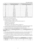
Page 17: ...24 8 27 8 31 34 3 37 8 41 5 45 4 49 4 53 6 window mounted 5 2 6 1 7 7 9 8 9 10 11 2 12 4 13 6 15 16 3 17 8 19 3 wall mounted 1 6 1 9 2 1 2 4 2 8 3 1 3 4 3 8 4 2 4 6 5 5 5 6 ceiling mounted 1 1 1 3 1 4 1 6 1 8 2 1 2 3 2 6 2 8 3 1 3 4 3 7 4 3 Maintenance notes Check whether the maintenance area or the room area meet the requirement It s only allowed to be operated in the rooms that meet the requirem...

Page 18: ...set point for startup of the optional electric heater Step 1 Optional electric heater installation Optional electric heater should be installed with monobloc unit in series The optional electric heater could be 1group or 2 group and only works of space heating Step 2 Electric wiring work AC contactor should be installed to XT2 KM1 1 group electric heater or KM1 and KM2 2 group electric heater Step...

Page 19: ... Protective measures should be taken during discharging to avoid frost bites 3 When discharging is finished if vacuuming cannot be done immediately remove the hose to avoid air or foreign matters entering the unit 4 Vacuuming when discharging is finished use hoses to connect the charging valve manometer and vacuum pump to vacuum the unit ...

Page 20: ...igerant but the use of detergents containing chlorine shall be avoided as the chlorine may react with the refrigerant and corrode the copper pipe work 6 If a leak is suspected all naked flames shall be removed extinguished If a leakage of refrigerant is found which requires brazing all of the refrigerant shall be recovered from the system or isolated by means of shut off valves in a part of the sy...

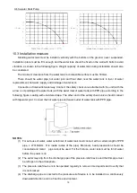
Page 21: ...nce coefficient L Z L Total length of circulating water pipeline Z Height difference of circulating inlet and outlet of water tank Resistance coefficient can be 0 05 in estimate pressure of the water column of 5 meters Flow of circulating water pump Circulating water flow of a single unit quantity Model Circulating water resistance kPa Circulating water resistance m GRS Cm18PdRe NhA M 27 2 7 NOTIC...

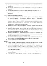
Page 22: ...e water inlet of water tank with PPR pipe according to the following figure sealing with unsintered tape The other end of the safety check valve should connect with tap water joint Connect the hot water pipe and water outlet of water tank with PPR pipe NOTES 1 For safe use of water water outlet inlet of water tank must connect with a certain length of PPR pipe L 70 R2 cm R is inside radius of the ...

Page 23: ... water tank safety check valve filter and cut off valve must be installed for the water inlet pipe according to the installation sketch of the unit At least a cut off valve is needed for the water outlet pipe 4 Installation of blow off pipes at the bottom of water tank connect a piece of PPR pipe with drainage outlet to floor drain A cut off valve must be installed in the middle of the drainage pi...

Page 24: ... copper wires 6 Connection of power cable to the electric cabinet of the unit 7 Power cables should be laid out through cabling trough conduit tube or cable channel 8 Power cables to be connected into the electric cabinet must be protected with rubber or plastic to prevent scratch by edge of metal plate 9 Power cables close to the electric cabinet of the unit must be fixed reliably to make the pow...

Page 25: ...led by professional technicians 5 The specifications of the breaker and power cable listed in the table above are determined based on the maximum power maximum amps of the unit 6 The specifications of the power cable listed in the table above are applied to the conduit guarded multi wire copper cable like YJV XLPE insulated power cable used at 40 and resistible to 90 see IEC 60364 5 52 If the work...

Page 26: ...Air to water Heat Pump 23 11 2 Electric Wiring 11 2 1 Wiring principle Refer to Section 9 6 11 2 2 Electric wiring The wiring diagram stuck to the unit always prevails ...

Page 27: ...nstaller are real If not debugging will be refused 2 Is there written notice in which amendment items are shown in respect of unqualified installation 3 Are Application for Installation and Debugging list filed together No Pre check 1 Is appearance of the unit and internal pipeline system ok during conveying carrying or installation 2 Check the accessories attached with the unit for quantity packa...

Page 28: ... be performed unless all installation items are qualified If there is any problem it must be solved firstly The installer will be responsible for all costs for delay of debugging and re debugging incurred by any problem which is not solved immediately Submit schedule of amending reports to installer Is the written amending report which should be signed after communication provided to installer Yes...

Page 29: ...llation and debugging are in accordance with the requirements a problem of power supply and electric control system b problem of load calculation c outdoor refrigerant system d noise problem e problem of indoor and piping system h other problems During operation it is needed to charge for the maintenance due to non quality problems such as incorrect installation and maintenance Acceptance Is the u...

Page 30: ...supply or terminal Malfunction of relay There is air in water pipe Find out the reasons and repair Replace relay Evacuate Compressor starts or stops frequently Poor or excess refrigerant Poor circulation of water system Low load Discharge or add part of refrigerant Water system is blocked or there is air in it Check water pump valve and pipeline Clean water filter or evacuate Adjust the load or ad...

Page 31: ...cian is completely familiar with the equipment and all its detail It is recommended good practice that all refrigerants are recovered safely Prior to the task being carried out an oil and refrigerant sample shall be taken in case analysis is required prior to re use of reclaimed refrigerant It is essential that electrical power is available before the task is commenced 1 Become familiar with the e...

Page 32: ...perse any released refrigerant and preferably expel it externally into the atmosphere 13 4 Notice before Seasonal Use 1 Check whether air inlets and air outlets of units is blocked 2 Check whether ground connection is reliable or not 3 If unit starts up after not operating for a long time it should be power on 8 hours before operation starts so as to preheat the outdoor compressor 4 Precautions fo...

Page 33: ......

Reviews: