background image

VRF Protocol Gateway


19 


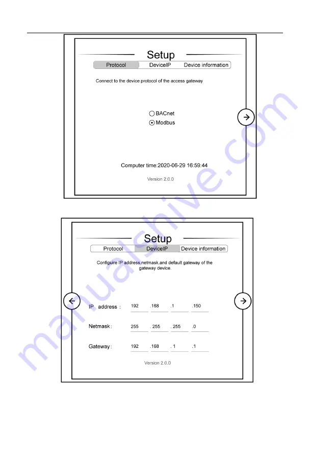
Fig. 7.12 Selection of protocol function 


Fig. 7.13 Setting interface of network parameters 

Summary of Contents for ME30-24/D1

Page 1: ...Owner s Manual Original Instructions VRF Protocol Gateway Model ME30 24 D1 BM ...

Page 2: ... functions introduced in this manual are only applicable to specific products all the illustrations and information in this manual are only for reference and the control interface should be subject to the actual interface 3 In order to better meet the customers demand our company will improve the product continuously and we have the right to conduct necessary modification at any time due to the re...

Page 3: ...tion 8 6 1 Building Management System BMS 8 6 2 Internet Topological Graph 8 7 Product Installation 10 7 1 Product Size and Spatial Size for Electric Control Cabinet Installation 10 7 2 Gateway and BMS adopt Modbus RTU Protocol Communication Connecting Method 11 7 3 Gateway and BMS adopt Modbus RTU Protocol Communication Connecting Method 14 8 BACnet Protocol 21 8 1 Structure of BACnet Protocol 21...

Page 4: ...cause fire hazard or serious injury As for above special places please adopt special air conditioner with anti corrosive or anti explosion function 2 User Notice Dear customer Please read this manual carefully prior to installation and operation and strictly observe all installation and operation instructions covered in the manual Special attentions shall be paid to the following marks WARNING Thi...

Page 5: ...otherwise this device would work improperly or even be damaged 2 Be sure this device is setup in place otherwise it would result in communication fault 3 Be sure the communication line is connected to the correct interface otherwise it would result in communication fault 4 After connection lines should be protected with insulating tape to avoid oxidation and short circuits 5 Risk of explosion if b...

Page 6: ...rameter Specifications 3 2 1 Gateway TCP IP Parameter Default IP Address 192 168 1 150 Subnet Mask 255 255 255 0 Default gateway 192 168 1 1 CAUTION After the TCP IP parameters are altered the gateway should be restarted then the parameters can come into effect 4 Parts and Assembly This kit includes the following parts Please check before installation Gateway 1 set Instruction manual 1 set 5 Intro...

Page 7: ...protocol RS485 1 comm port connect to the BMS terminal through a two core communication line to realize the communication connection between the gateway and the BMS terminal or the connection between adjacent gateways RS485 2 comm port this device will not use this communication interface temporarily USB and SD card port this device will not use this interface temporarily Ethernet comm port ETH0 r...

Page 8: ...ives data on the 485 bus it blinks TX When the gateway sends data to the 485 bus it blinks RS485 2 RX This device does not use this LED indicator TX This device does not use this LED indicator STAT When power supply of Gateway is normal it is on BEAT When Gateway is running normally it blinks BACKUP This device does not use this LED indicator 5 3 Button SHT DWN When the fourth digit of DIP switch ...

Page 9: ...us Specific meaning shall refer to the specification in Fig Internet topological graph The No 1 dial up button in function dial up machine shall be used in the setting in the matched resistance of CAN2 bus in this gateway When the gateway is at the top end of CAN2 bus the gateway shall be with the matched resistance then dial the No 1 function dial up machine to 1 When the gateway is not at the to...

Page 10: ...ction dialer is used for setting the matching resistance of the gateway of 485 bus When the controller is at the beginning end of the 485 bus the controller needs to be set to be with matching resistance then the second bit of function dialer is set to 1 when the controller is not at the beginning end of the 485 bus set the controller to be without matching resistance and set the dial code to 0 Fi...

Page 11: ...ation Dial the fourth digit of the DIP switch code to 1 hold SHT DWN button for 5s to restore the default information of factory setting of the gateway 6 Application 6 1 Building Management System BMS This gateway has provided Modbus RTU Modbus TCP and BACnet standard protocols which can connect to building management system BMS Realizing the monitoring of Gree units of CAN bus by building managem...

Page 12: ...via the network cable CAN1 network L3 shown in Fig 6 2 is CAN1 bus which consists of network and all the outdoor units and indoor units of system one CAN1 network can connect to 80 sets of indoor units at most CAN2 network L2 shown in Fig 6 2 is CAN2 bus which consists of gateway and master outdoor unit of system one CAN2 network can connect to 16 sets of outdoor units and 255 sets of indoor units...

Page 13: ...ost if there a re other 485 equipment in the 485 bus the connectable gateway should reduce accordingly 2 It is recommended that the connecting quantity of gateway of 485 bus n is less or equal to 16 7 Product Installation 7 1 Product Size and Spatial Size for Electric Control Cabinet Installation 7 1 1 Product Size Fig 7 1 Gateway product size chart Notice for installation and operation 1 Ensure t...

Page 14: ...ic control cabinet the front of gateway shall be hung upward and fixed with 4 screws See the following fig for reference Fig 7 2 Gateway installation guide WARNING Power cord and communication line of Gateway must conduct routing separately the distance shall be over 15cm otherwise it might lead to Gateway communication malfunction The thin real line shown in the figure is communication wire and w...

Page 15: ...ommunication between gateway and BMS via Modbus Shielding light general PVC jacket twisted pair L 800 2 0 75 IEC 60227 5 2007 When the communication distance exceeds 800m a PV isolation relay should be added 7 2 2 Communication Connection Method NOTICE All communication connection lines under Gateway must be in series connection star connection shall not be adopted ...

Page 16: ... when the quantity of connected gateway exceeds 30 or the communication distance exceeds 800m one more PV isolation relay should be added and connect the R and R terminals of PV isolation relay to the RS485 1 communication interfaces R and R of the adjacent gateway Fig 7 4 Installation of relay ...

Page 17: ...Connect the RS485 1 communication interfaces R and R of the gateway to the RS485 1 communication interfaces R and R of the second gateway with communication cable as shown in Step in the figure Step 3 Connect other gateways in turn as shown in Step in the figure 7 3 Gateway and BMS adopt Modbus RTU Protocol Communication Connecting Method 7 3 1 Material Selection for Communication Iine 1 Model sel...

Page 18: ...teway and AC units Wire diameter mm2 Wire standard Remark Light weight normal PVC jacket twisted copper wire L 500 2 0 75 IEC 60227 5 2007 Total communication length shall not exceed 500m 7 3 2 Communication Connection Method 1 Communication connection between Gateway and BMS Fig 7 6 Connecting method between gateway and router ...

Page 19: ... 16 Fig 7 7 Connecting method of gateway NOTICE All communication connection lines under Gateway must be in series connection star connection shall not be adopted 7 3 3 Communication Connection Configuration 1 Communication line connection between Gateway and PC Connection diagram between Gateway and PC user side ...

Page 20: ...ll go through router to connect to PC Fig 7 9 Gateway connects to personal computer via router 2 Communication line connection between Gateway and AC units When gateway is connected to main control unit of ODU ODU with the address dial up of 0 must be connected CAN G1 G2 D1D2 G1G2 1 2 ON ON Main control Unit of ODU Subordinate Unit of ODU Fig 7 10 Communication connection between gateway and unit ...

Page 21: ...150 default user name config password config as shown below Fig 7 11 Log on interface Setting of gateway protocol functions After inputting user name and password click the arrow to enter the setting interface as shown in Fig 7 12 7 13 and 7 14 in the setting interface 1 you can select the protocol function in the setting interface 2 you can set the IP parameters of gateway in the setting interfac...

Page 22: ...VRF Protocol Gateway 19 Fig 7 12 Selection of protocol function Fig 7 13 Setting interface of network parameters ...

Page 23: ...oadcast address such as 192 168 1 255 it is not recommended to set the address by user otherwise it may cause problems such as the network is not accessible subnet mask of gateway default gateway gateway name gateway ID User can set by himself herself according to the actual needs After setting click the arrow the interface will pop up a window to ask Whether to restart the gateway to make the set...

Page 24: ...th property to represent any functions of building self control equipment thus provide a standard method to represent building self control equipment The Gateway defines 9 objects the enumeration number name and application sample of these objects are introduced as follows No Object name Application sample 0 Analog Input Sensor input 1 Analog Output Control output 2 Analog Value The set valve valu...

Page 25: ...after data conversion ID value of BACnet object BACnet ID P N 256 D 256 512 M 256 512 4 For example indoor ambient temperature of object IndoorUnitAmbientTemp_01_01_01 its BACnet object ID is IndoorUnitAmbientTemp_01_01_01 with the following meaning BACnet object ID 32bits 10 bits 3 bits 2 bits 9 bits 8 bits Reserved Model series assigned to be 0 M Equipment type 01 02 03 D Equipment migration N P...

Page 26: ...demonstrate the setting of TCP IP 1 Left click the icon Start on the computer When a new window pops up left click Settings to enter Windows Settings 2 Left click Network Internet in the following picture to enter the interface of Network Internet See in the picture below Fig 9 1 Windows settings ...

Page 27: ... Center in the following picture See in the picture below Fig 9 2 Network and Sharing Center 4 Find Ethernet in the following picture Left click Ethernet and enter the interface of Ethernet Status See in the picture below Fig 9 3 Ethernet settings selection ...

Page 28: ...VRF Protocol Gateway 25 5 Left click Properties in the following picture and enter the interface of Ethernet Properties See in the picture below Fig 9 4 Ethernet attribute selection ...

Page 29: ...tocol Version 4 TCP IPv4 See in the picture below Then left click Properties as shown in the picture to enter the interface of Properties of Internet Protocol 4 TCP IPv4 See in the picture below Fig 9 5 Internet Protocol Version 4 TCP IPv4 Properties ...

Page 30: ...ocol Version 4 TCP IPv4 as shown below change the IP address subnet mask default gateway as required address of network equipment for connecting Gateway must be the same as the network address of Gateway ME30 24 D1 BM Generally DNS remains unchanged Fig 9 6 Ethernet IP parameter settings ...

Page 31: ......

Reviews: