BACnet Gateway Kit for Central Air Conditioners
7
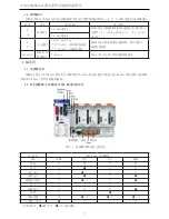
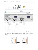
2�4 General Drawing
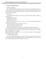
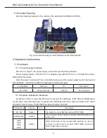
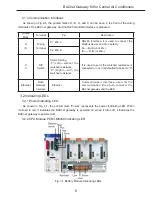
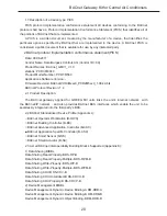
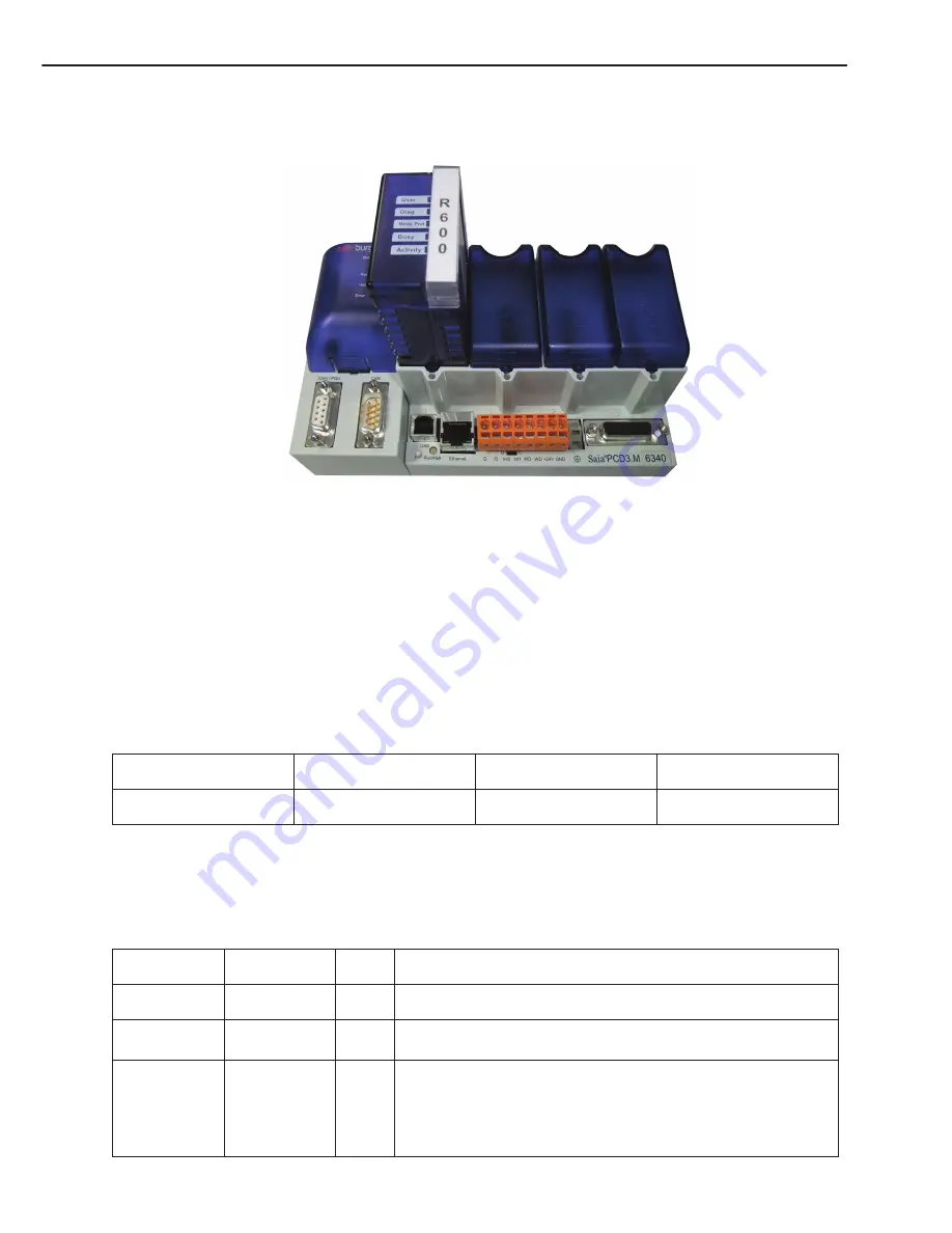
See the following drawing for the outline of the whole BACnet MG30-24/D1(B)
Fig. 2-5 Outline Drawing of the Whole BACnet MG30-24/D1(B)
3 Operation Instructions
3�1 Interfaces
3�1�1 Power Supply Interface
As shown in Fig.2-5, the power supply is input through the wiring terminal.
Power Supply: 24VDC -20/+25% incl. 5% ripples as per EN/IEC 61131-2, 175mA/4.2W normal,
500mA/12W maximum.
Note: the power cord mustn’t be connected reversely and the power supply mustn’t be beyond
the specified l, otherwise the BACnet gateway would be damaged.
Printed Mark
Terminal
Pin
Description
+24V GND
Wiring Terminal
+24VDC
24V DC Input
3.1.2 Module Installation Interfaces
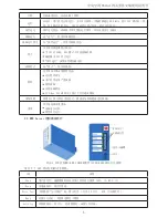
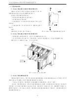
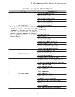
As shown in Fig.2-5, when the left cover is opened, the interfaces of M1, M2 and Batt Module
can be seen; when the right cover is opened, the interfaces from left to right are Slot0, Solt1, Slot2
and Slot3, in which case, PCD3.R600 has been inserted into Slot0.
Printed Mark
Terminal
Pin
Description
M1, M2
Socket
/
It is used to connect BACnet module PCD7�R560
Batt Module
Socket
/
It is used to connect battery module PCD3.M6340 (incl.
button cell)
Slot0
Slot1
Slot2
Slot3
Socket
/
Slot0 (at the side of the nearest USB interface) is used to
connect the Web server module PCD3.R600 into which
PCD7.R-SD1024 is inserted.

