BACnet Gateway Kit for Central Air Conditioners
8
3�1�3 Communication Interfaces
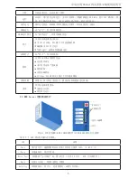
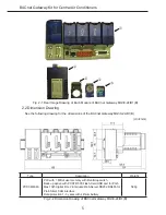
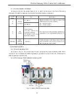
As shown in Fig.2-5, the printed marks D, /D, O, and C can be seen in the front of the wiring
terminals of the BACnet gateway, and the RJ45 standard interface is prepared.
Printed
Mark
Terminal
Pin
Description
D
/D
Wiring
Terminal
P1: 485
A
RS485 Interface, it is used to connect the
Modbus device and of no polarity.
D——R+/D+(or 485+);
/D——R-/D-(or 485-)
P2: 485
B
O
C
DIP
Switch
Switch Setting
“0”(Left)—without the
matched resistance
“C”(Right)—with the
matched resistance
It is used to set if the matched resistance is
connected or not. It is defaulted to be set to “C”
Ethernet
RJ45
Network
Interface
Ethernet
Communication Interface, used for the
communication line which connects the
BACnet gateway and the BAS.
3�2 Indicating LEDs
3�2�1 Power Indicating LED
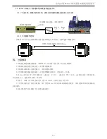
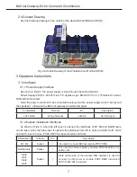
As shown in Fig. 3-1, the printed mark “Power” represents the power indicating LED. When
it turned to red, it indicates the BACnet gateway is powered on; when it turns off, it indicates the
BACnet gateway is powered off�
3.2.2 CPU Module PCD3.M6340 Indicating LED
Fig. 3-1 Battery Module Indicating LEDs

