background image

33

Air to Water Heat Pump 

Service Manual- Versati II Series

CONTROL

3�3�6 Key Lock

At the homepage, by pressing the Up/Down keys simultaneously for 5 seconds, it is able to activate or 

deactivate this function. When it is activated, any key operation is ineffective.

3�4 Precautions

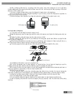
Install the control following instruction shown in the figure below.


No�

1

2

3

4

Name

LCD

Communication line

Screws ST4.2X16

Rubber pad

Installation Steps

Step 1: draw the communication lines out from the LCD

Step 2: take four screws away from the rubber pad.

Step 3: remove the rubber pad off the LCD.

(3) After LCD is removed, unplug communication line according Fig 4.

4 CONTROL WIRING DESIGN

Indoor Unit 
Eletric box

Main board 

Diplay  board 

CN4

AP

CN6

4

4

3

CN5

CN5

CN66 AP1

Main board 

Outdoor Unit 
Eletric box

Long-distance

 Minitor PC

Installation Instruction :

(1) Wired controller connects to terminal CN6 on mainboard of indoor unit by 4-core communication line.

(2) The indoor unit connects to outdoor unit by 3-core communication line. Wiring terminal of indoor unit is 

CN5 and that of the outdoor unit is CN66.

(3) Remote monitoring device connects to terminal CN4 of Display Board by 4-core communication line.

Summary of Contents for Versati II

Page 1: ...AIR TO WATER HEAT PUMP SERVICE MANUAL Versati T1 R410A 50Hz GC201308 II ...

Page 2: ...her dependent Heating Mode 4 4 PRODUCT DATA 5 4 1 Product Data at Rated Condition 5 4 2 Operation Range 7 4 3 Electrical Data 8 5 PIPING DIAGRAM 9 UNITS CONTROL 11 1 OPERATION FLOWCHART 11 2 MAIN LOGIC 12 2 1 Defrosting Mode 12 2 2 Water side Auto Anti freezing in Winter 12 2 3 Control of Heating Tape on Chassis 12 2 4 Control of Fan 12 2 5 Control of Compressor 12 2 6 Control of Electric Expansio...

Page 3: ...C WIRING WORK 47 2 1 Wiring Principle 47 2 2 PCB Outline 48 2 3 Electric Wiring Design 50 UNITS MAINTENANCE 60 1 ERROR CODE LIST 60 2 FLOW CHART OF TROUBLESHOOTING 64 3 DIAGNOSIS OF DRIVING 68 3 1 Diagnosis Flowchart of Driving of Single phase Unit and Three phase Unit 68 4 DISASSEMBLY AND ASSEMBLY PROCEDURE OF MAIN PARTS 72 5 EXPLODED VIEWS AND PART LIST 82 5 1 Outdoor Exploded View and Part List...

Page 4: ...1 Air to Water Heat Pump Service Manual Versati II Series PRODUCT PRODUCT ...

Page 5: ... Water Tank Model Product Code Nominal Cubage L Appearance SXVD200LCJ A K ER20000160 200 SXVD200LCJ A M ER20000240 200 SXVD300LCJ A K ER20000180 300 SXVD300LCJ A M ER20000250 300 SXVD200LCJ2 A K ER20000170 200 SXVD200LCJ2 A M ER20000260 200 SXVD300LCJ2 A K ER20000190 300 SXVD300LCJ2 A M ER20000270 300 2 NOMENCLATURE 2 1 Main Unit G RS C Q 16 Pd Na B K I 1 2 3 4 5 6 7 8 9 10 NO Description Options ...

Page 6: ... indoor unit the water absorbs heat and its temperature increases while the refrigerant releases heat and is condensed With the help of wired controller the outflow temperature can meet the user s requirement Through the control of valve the high temperature water in the system is connected with the coil pipe of bearing water tank and exchanges heat with the water in the water tank so that the tem...

Page 7: ...nt recovery and debugging of the unit 3 10 Silent Mode Silent mode is available in cooling heating and water heating mode In silent mode the outdoor unit will reduce the running noise via automatic control 3 11 Disinfection Mode In this mode the water heating system can be disinfected When starting up the disinfection function and setting corresponding time to meet the requirement of disinfection ...

Page 8: ...4 EER COP 2 W W 2 8 3 5 2 8 3 45 2 65 3 5 Refrigerant charge volume kg 3 2 3 2 3 2 Sanitary water Temperature 40 80 40 80 40 80 Sound Pressure Level cooling dB A 55 55 57 heating dB A 57 57 58 Connecting pipe Gas inch mm φ5 8 15 9 φ5 8 15 9 φ5 8 15 9 Liquid inch mm φ3 8 9 52 φ3 8 9 52 φ3 8 9 52 Dimensions W D H Outline mm 900 412 1345 900 412 1345 900 412 1345 Packaged mm 998 458 1515 998 458 1515...

Page 9: ... 25 45 Low temperature cycle Pump Type Water cooled Water cooled Water cooled Nr of speed 3 3 3 Power input W 200 200 200 Water flow limit LPM 7 5 7 5 7 5 Electric Heater Operation Automatic Automatic Automatic Steps 2 2 2 Capacity kW 3 3 3 Combination kW 3 3 3 3 3 3 Power input Ph V Hz 1 230 50 1 230 50 1 230 50 Sound pressure level dB A 31 31 31 Connecting pipe Gas inch mm φ5 8 15 9 φ5 8 15 9 φ5...

Page 10: ...Power W 3000 Cool Water Inlet Pipe Outer diameter mm DN15 inch 1 2 Screw thread spec 1 2 Female BSP Hot Water Outlet Pipe Outer diameter mm DN15 inch 1 2 Screw thread spec 1 2 Female BSP Circulation Water Inlet Outlet Pipe Outer diameter mm DN20 DN20 inch 3 4 3 4 Screw thread spec 3 4 Female BSP 3 4 Female BSP Water Inlet Outlet Heat Pump Pipe Outer diameter mm DN20 inch 3 4 Screw thread spec 3 4 ...

Page 11: ...ower supply must be of rated voltage of the unit and special electrical line for air conditioning All electrical installation shall be carried out by professional technicians in accordance with the local laws and regulations Ensure safe grounding and the grounding wire shall be connected with the special grounding equipment of the building and must be installed by professional technicians The spec...

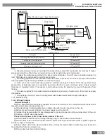
Page 12: ...plate heat exchanger 11 flow switch 10 electric heater 9 air vent valve 8 pump 18 water tank 12 3 way valve 17 other thermal system 16 radiator 15 under floor heating R6T water tank temperature sensor 1 R4T returning water temperature sensor R1T plate outlet temperature sensor t R1T R3T t R5T t R4T t t R6T t R2T 9 19 expansion tank 20 safety valve R2T Liquid line temperature sensor R5T leaving wat...

Page 13: ...10 Air to Water Heat Pump Service Manual Versati II Series CONTROL CONTROL ...

Page 14: ...l Electric Expansion Valve Control Error Indication Outdoor fan Motor Control Compressor Control Error Indication Water Flow SwitchControl YES NO NO Error Indication YES YES YES Error Indication 4 Way Valve Control Error Indication 3 Way Valve and 2 Way Valve Control WaterHeating Operation Water Pump Control Electric Expansion Valve Control Error Indication Outdoor fan Motor Control Compressor Con...

Page 15: ...n of the unit anti freezing operation will be started by indoor electric heater two sets 2 3 Control of Heating Tape on Chassis When heating operation starts in low temperature in order to prevent the condensation water generated by defrosting from freezing in chassis which will incur malfunction of drainage the heating tape is installed in chassis If the ambient temperature is lower than 0 when t...

Page 16: ...p Service Manual Versati II Series CONTROL 3 WIRED CONTROLLER 3 1 Dimension 163 164 4 129 4 17 5 105 106 4 40 7 21 3 2 Function 3 2 1 External View 1 2 3 10 11 12 13 14 15 9 4 5 6 7 8 This effect drawing is just for reference ...

Page 17: ...13 4 24 Wednesday VERSATI Mode Auxiliary func Error state 40 20 No Off No Yes T water out Home Page Yes T water out T outdoor Key lock 40 20 No Mode Auxiliary func Off No Error state 8 30 2013 4 24 Wednesday VERSATI FUNC PARA VIEW GEN No Item Functional Description 1 Mode It is intended to access to the actual running mode 2 Auxiliary Func It indicates the auxiliary function note 1 3 Error state I...

Page 18: ...ating LED will light off Notes The unit is defaulted to be OFF when energized for the first time The ON OFF key operation works only at the home page and the standby page When the Holiday mode or the Emergen mode is activated the ON OFF key operation will become ineffective When the Forced Heating or Forced Cooling is activated it will be deactivated by pressing the ON OFF key and then press the O...

Page 19: ...m is available only when Remote Sensor is set to With 3 Fast hot water Fast hot water On Off Off When the water tank is unavailable this function will be reserved and the LCD will display Reserved 4 Water out temperature control T water ctrl High temp Low temp Low temp 5 Cool hot water Cool hot water Cool Hot water Cool 6 Heat hot water Heat hot water Heat Hot water Heat When the water tank is una...

Page 20: ...rl state then configure it through the Up Down key Notes If Remote sensor is set to With T out water and T room are available While if Remote Sensor is set to Without only T out water is selectable This setting will be memorized upon power failure 3 3 2 3 Fast Hot Water Go to the FUNCTION page and locate Fast hot water then configure it through the Up Down key On or Off Notes It works only when Wa...

Page 21: ...Down key it can be set to be On or Off Start time End time 08 30 17 30 8 30 2013 4 24 Wednesday QUIET TIMER Minute Save Notes Once it is activated it should be deactivated manually It will not be memorized and be defaulted to be off upon power failure The saved Start time and End time will be memorized upon power failure It is configurable no matter if the unit is in operation or not 3 3 2 9 Auto ...

Page 22: ...ce When Sanitize is activated Sanitize will show on the home page of the control until this operation is finished If this operation fails Sanitize fails will show In this case by pressing any key Sanitize failure will be cleared or it will be always there When Sanitize is activated it will quit upon Communication error with the indoor unit or Water tank heater error 3 3 2 12 Weekly Timer 1 At the ...

Page 23: ... time Similarly the preceding period must be earlier than its following period When Weekly timer has been set successfully by changing FCU Water tank Ctrl state or T water ctrl then the temperature set point for Weekly timer will be automatically changed to the set point of last setting For instance if Heat is set for Monday of Weekly timer FCU is set to With and the T water out is 20 by resetting...

Page 24: ...tank Ctrl state Set Mode Object Range Default Accuracy T water out Cool Water out temperature for cooling WT cool 7 25 With FCU 18 25 Without FCU 7 With FCU 18 Without FCU 1 Heat Water out temperature for heating WT heat High temp 25 55 45 1 Low temp 25 45 35 1 T room Cool Room temperature for cooling RT cool 18 30 20 1 Heat Room temperature for heating RT heat 18 30 26 1 3 3 2 13 Clock Timer 1 At...

Page 25: ...tank 40 80 104 176 50 122 Start time Start time 00 00 23 59 08 30 End time End time 00 00 23 59 17 30 3 3 2 14 Temp Timer 1 At the homepage by pressing the Function key access to the FUNCTION page and then locate where Temp timer is after that press OK key to go to the TEMP TIMER setting page 2 At the TEMP TIMER setting page by the Left Right key select the desired parameter and then by the Up Dow...

Page 26: ...me as listed in the following table No Full Name Displayed Name Range Default Accuracy 1 Segments for floor debug Segments 1 10 1 1 2 First temperature for floor debug Period 1 temp 25 35 77 95 25 77 1 1 3 Segment temperature difference for floor debug ΔT of segment 0 72H 0 12H 4 Segments duration for floor debug Segment time 2 10 36 50 5 41 1 1 3 After the above setting is finished by pressing th...

Page 27: ... be deactivated Weekly timer Clock timer and Temp timer also cannot be activated or will be deactivated if being activated At the Emergency mode commands from the Thermostat is ineffective At the Emergency mode only one running mode between Heat and Hot water is allowed This function can be activated only when the unit is OFF or a dialog box will pop up warning Please turn off the system first Und...

Page 28: ...ill be memorized upon power failure 3 3 2 22 Water Tank Go to the FUNCTION page and locate Water tank then configure it through the Up Down key With or Without Notes It will be memorized upon power failure This setting is allowed only when the unit is turned off 3 3 2 23 Tank Sensor Go to the FUNCTION page and locate Water tank then configure it through the Up Down key 1 or 2 When the water tank i...

Page 29: ...l run normally if not the control will turn off the unit and back to the homepage In this case any key operation is ineffective except for the combined key operation or a dialogue box will pop up warning Keycard uninserted It will not be memorized upon power failure 3 3 3 Parameter Setting Parameter Set 3 3 3 1 User Parameter Setting 1 At the homepage it is able to go to the PARAMETER page by pres...

Page 30: ...g Lower RT Heat 18 21 64 70 20 68 13 Upper limit water out temperature at the auto mode for heating Upper WT Heat 46 55 High temp 30 35 Low temp 115 131 High temp 86 95 Low temp 48 118 High temp 35 95 Low temp 14 Lower limit water out temperature at the auto mode for heating Lower WT Heat 36 45 High temp 25 29 Low temp 97 113 High temp 77 84 Low temp 40 104 High temp 29 84 Low temp 15 Lower limit ...

Page 31: ...ssor running state Compressor On Off Fan 1 running state Fan 1 On Off Fan 2 running state Fan 2 On Off IDU water pump running state IDU WP On Off Solar water pump running state Solar WP On Off Tank heater running state Tank heater On Off 2 Way valve running state 3 way valve On Off Crankcase heater running state Crankc heater On Off Chassis heater running state Chassis heater On Off Defrost Defros...

Page 32: ... page it is able to view each parameter No Full Name Displayed Name Status 1 Outdoor temperature T outdoor Exact values 2 Suction temperature T suction 3 Discharge temperature T discharge 4 Defrost temperature T defrost 5 Liquid temperature T liquid 6 Water in temperature T water in 7 Plate exchanger water out temperature T waterout PE 8 E heater water out temperature T waterout EH 9 Water tank te...

Page 33: ...n temperature sensor error Suction sensor F5 Outdoor fan error Outdoor fan EF Compressor internal overload protection Comp overload H3 High pressure protection High pressure E1 Low pressure protection Low pressure E3 High discharge protection Hi discharge E4 Incorrect capacity DIP switch setting Capacity DIP c5 Communication error between indoor and outdoor unit ODU IDU Com E6 High pressure sensor...

Page 34: ...ion error drive main com P6 Radiator or IPM or PFC module overtemperature Overtemp mod P8 Radiator or IPM or PFC module temperature sensor error T mod sensor P7 Charging circuit error Charge circuit PU Incorrect AC voltage input AC voltage PP Drive board temperature sensor error Temp driver PF AC contactor protection or input zero crossing error AC contactor P9 Temperature drift protection Temp dr...

Page 35: ...Off On 6 Back light Back light Lighted Energy save Energy save On it always lights on Eco it lights off when there is no key operation for 1 minute a n d w i l l l i g h t s o n where there is any key operation 3 3 5 1 Clock Setting 1 At the homepage by pressing GEN access to the GENERAL SET page Then select Time Date at this page After that go to the Time Date setting page by pressing the OK key ...

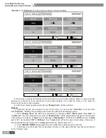
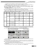
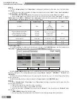
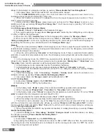
Page 36: ... 2 take four screws away from the rubber pad Step 3 remove the rubber pad off the LCD 3 After LCD is removed unplug communication line according Fig 4 4 CONTROL WIRING DESIGN Indoor Unit Eletric box Main board Diplay board CN4 AP CN6 4 4 3 CN5 CN5 CN66 AP1 Main board Outdoor Unit Eletric box Long distance Minitor PC Installation Instruction 1 Wired controller connects to terminal CN6 on mainboard ...

Page 37: ...34 Air to Water Heat Pump Service Manual Versati II Series INSTALLATION INSTALLATION ...

Page 38: ...he water immediately 2 When recharging the hydraulics system pressure should be not more than 2 5Bar 1 1 3 Installation Positions of Water Tank The insulated water tank should be installed and keep levelly within 5m and vertically within 3m from the Indoor unit It can be installed in the room Standing water tank must be installed vertically with the bottom on the ground never suspended Installatio...

Page 39: ...i II Series INSTALLATION 1 3 Dimension Data and Installation Guide 1 3 1 Outdoor GRS CQ12Pd NaB K O GRS CQ14Pd NaB K O GRS CQ16Pd NaB K O 1345 1326 900 572 340 378 412 1 3 2 Indoor GRS CQ12Pd NaB K I GRS CQ14Pd NaB K I GRS CQ16Pd NaB K I 500 324 900 ...

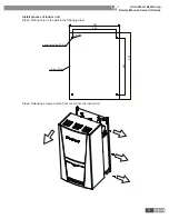
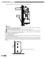
Page 40: ... Manual Versati II Series INSTALLATION Install process of indoor unit Step1 Drilling hole on the wall in the following draw 500 463 900 823 unit outline expansion bolt hole Step2 Releasing screws detach front cover from the indoor unit ...

Page 41: ...it as close as possible to outdoor unit Level distance between connection pipes can not exceed 30m and vertical distance can not exceed 15m 1 3 3 Installation of Insulated Water Tank 1 3 3 1 Installation Measure The insulated water tank should be installed and keep levelly within 5m and vertically within 3m from the Indoor unit It can be installed in the room Standing water tank must be installed ...

Page 42: ...h the water inlet of water tank with PPR pipe according to the following figure sealing with unsintered tape The other end of the safety check valve should connect with tap water joint Connect the hot water pipe and water outlet of water tank with PPR pipe Tap water Safety check valve Note For safe use of water water outlet inlet of water tank must connect with a certain length of PPR pipe L 70 R2...

Page 43: ...ter tank should also be hot water pipe PPR pipe with nominal out diameter of dn20 and S2 5 series wall thickness of 3 4mm being recommended If other insulated pipes are adopted refer to the above dimensions for out diameter and wall thickness Installation of circulating water inlet outlet pipes Connect the water inlet of unit with circulating outlet of water tank and water outlet of unit with circ...

Page 44: ...tion of waterway system meanwhile pay more attention to valves and pipe joints Ensure enough thickness of insulated cotton If necessary install heating device for pipeline to prevent the pipeline from freezing Hot water supplied from insulated water tank depends on pressure of water tap so there must be supply of tap water During using the cut off valve of cooling water inlet of water tank should ...

Page 45: ...es INSTALLATION 1 4 Installation Clearance Data 1000 2000 500 500 500 500 2000 250 200 1300 800 1 Water Volume and Pump capacity Note The water pump is three speed adjustable maximum medium minimum In most case we strongly recommended to set speed as maximum ...

Page 46: ...en installing location of indoor unit and the highest spot of water system Ensure that the volume of water system is lower than the maximum volume required in the above figure If it exceeds the range the expansion vessel does not meet the installing requirement Installation height difference1 Water volume 280L 280L 7 m Adjustment is not necessary 1 Pre set pressure needs to be adjusted according t...

Page 47: ...at is the action pressure of safety valve e The expansion factor of water the difference between the expansion factor of the original water temperature and that of highest water temperature Water expansion factor in different temperature Temperature Expansion factor e 0 0 00013 4 0 10 0 00027 20 0 00177 30 0 00435 40 0 00782 45 0 0099 50 0 0121 55 0 0145 60 0 0171 65 0 0198 70 0 0227 75 0 0258 80 ...

Page 48: ...nnecting outdoor and indoor unit never pull the big and small joint of indoor unit with force so as to prevent the tubes of indoor unit from cracking and causing leakage Connecting pipe shall be supported by a rack without transmitting its weight to other units 2 Installation of Protective Layer on Connection Pipe To avoid condensate dew or water leakage on connecting pipe the air pipe and liquid ...

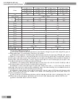
Page 49: ...CQ16Pd NaB K 5 8 3 8 7 5m 30m 0m 15m 50g m Note No additional charge of the refrigerant is need when the pipe length is less than 10 m if the pipe length is longer than 10m additional charge of the refrigerant is needed according to the table Example If 16kw model is installed at a distance of 25m 25 10 50 750g refrigerant should be added Rated capacity is based on standard pipe length and maximum...

Page 50: ...t be shut off Installer shall be responsible for any damage due to incorrect connection of the external circuit of the unit Caution MUST use copper wires 2 Connection of power cable to the electric cabinet of the unit Power cables should be laid out through cabling trough conduit tube or cable channel Power cables to be connected into the electric cabinet must be protected with rubber or plastic t...

Page 51: ... pin feedback signal DC_MOTOR2 DC fan 1 pin strong power supply 3 pin fan GND 4 pin 15V 5 pin control signal 6 pin feedback signal 4V1 4 way valve HEAT electric heating tape VA 1 e heater of chassis HPP high pressure switch LPP low pressure switch T SENSOR2 1 2hole pipe temperature 3 4hole environment 5 6 hole exhaust T SENSOR3 1 hole 3 3V 2 hole detection suction temperature sensor CN66 CN67 comm...

Page 52: ...r pump PUMP2 X14 live wire of solar water pump RUN X15 running indicator HEAT3 L X16 e heater of water tank HEAT1 L X17 e heater of indoor unit 1 HEAT2 L X18 e heater of indoor unit 2 ERR X19 error indicator 2V1_OFF X5 Electric magnetic 2 way valve1 is normally closed 2V1_ON X6 Electric magnetic 2 way valve1 is normally open 2V2_OFF X7 Electric magnetic 2 way valve2 is normally closed 2V2_ON X8 El...

Page 53: ...K 20K 20K 20K 20K Main Board Only For RT9 Water flow switch SW AP2 2 CN14 53 52 CN66 PE PE OUTDOOR UNIT CN5 RD BK XT2 39 38 37 36 35 34 XT2 33 32 31 30 8 3 way valve1 2 way valve2 2 way valve1 N L2 ON L1 OFF L1 OFF N L2 ON N L1 OFF L2 ON N L2 ON L1 OFF 12 11 10 9 8 7 6 5 4 3 2 1 4 6 N 2 1 L TC 6 4 N XT1 KM1 6 4 KM2 N CN2 CN1 CN3 CN10 CN12 CN11 CN13 CN15 X5 X6 X7 X8 X9 X10 X11 X12 CN25 RT1 RT2 RT3 ...

Page 54: ...ervice Manual Versati II Series INSTALLATION 2 3 2 Wiring Diagram Outdoor Unit GRS CQ12Pd NaB K O GRS CQ14Pd NaB K O GRS CQ16Pd NaB K O 2 3 3 Wiring Diagram Water Tank SXVD200LCJ A K SXVD200LCJ2 A K SXVD300LCJ A K SXVD300LCJ2 A K ...

Page 55: ...Service Manual Versati II Series INSTALLATION SXVD200LCJ A M SXVD200LCJ2 A M SXVD300LCJ A M SXVD300LCJ2 A M SXVD200LCJ A H SXVD200LCJ2 A H SXVD300LCJ A H SXVD300LCJ2 A H WP95A R WP85A R PE PE PE PE Thermostat1T hermostat2 Heater ...

Page 56: ... Water Heat Pump Service Manual Versati II Series INSTALLATION 2 3 4 Wiring Diagram Indoor and Outdoor Unit Including Field Wiring GRS CQ12Pd NaB K GRS CQ14Pd NaB K GRS CQ16Pd NaB K Other auxiliary heat sources ...

Page 57: ...d 1 power supply for Water tank electric heater N 2 1 N L Connecting external electric power supply for Indoor Unit Terminal Board 2 Terminal board 3 27 28 23 22 21 Thermostat 1 24 25 26 6 5 4 2 way value 2 2 way value 1 1 9 8 7 3 way value 1 3 way value 2 10 11 12 15 14 13 16 17 18 19 20 Connection for Client water s AC contactor Connection for Indicating lihgt Connection for Accident lihgt Gate ...

Page 58: ...oor loop in cooling mode when fan coil unit is equipped for cooling operation General Information Type Power Operating Mode Supported NO 2 wire 230V 50Hz AC Closing water flow Yes Opening water flow Yes NC 2 wire 230V 50Hz AC Closing water flow Yes Opening water flow Yes 1 Normal Open type When electric power is NOT supplied the valve is open When electric power is supplied the valve is closed 2 N...

Page 59: ...formation Type Power Operating Mode Supported SPDT 3 wire 230V 50Hz AC Selecting Flow A between Flow A and Flow B Yes Selecting Flow B between Flow B and Flow A Yes 1 SPDT Single Pole Double Throw Three wires consist of Live1 for selecting for selecting Flow B and Neutral for common 2 Flow A means water flow from the indoor unit to under floor water circuit 3 Flow B means water flow from the indoo...

Page 60: ...ween 21 and 22 and then connect the Gate controller Installation Guide follow as GRS CQ12Pd NaB K I GRS CQ14Pd NaB K I GRS CQ16Pd NaB K I 19 20 Gate controller GREE does not supply this section 19 20 50 XT XT 2 3 11 Remote Air Temperature Sensor Front side Back side Remote Air Temperature Sensor Doors NO NO NO NO 1 5 Meters YES AP1 RT9 CN1 15K CN15 Remote Air Environment Temp sensor Electric box P...

Page 61: ...25 24 21 22 23 XT3 Heat N Thermostat Thermostat L 230V 27 28 Cool Heat N Cool L 24V Fig 1 How to Wire Thermostat 1 Uncover the front cover of the indoor unit and open the control box 2 Identify the power specification of the thermostat if it is 230V find terminal block XT3 as NO 21 24 or NO 23 26 Otherwise if it is 24V find terminal block XT3 as NO 25 28 or NO 27 30 3 If it is Heating Cooling ther...

Page 62: ...59 Air to Water Heat Pump Service Manual Versati II Series MAINTENANCE MAINTENANCE ...

Page 63: ... breaks If it occurs for 3 times during one hour it is cleared by de energization If it occurs for less than 3 times it will be automatically cleared E5 Overload protection of compressor or driver error It is the compressor overload switch error or the compressor drive protection and please see the indicating lamp on the main board of the outdoor unit or the 88 nixie tube for the protection code D...

Page 64: ... sensor error The plug on temperature sensor is not correctly connected to the socket on mainboard The resistance of temperature sensor is not correct It will be automatically cleared after the failure is removed dH Heat exchanger leaving water temperature sensor error The plug on temperature sensor is not correctly connected to the socket on mainboard The resistance of temperature sensor is not c...

Page 65: ...p protection The resistance of temperature sensor is not correct The plug on temperature sensor is not correctly connected to the socket on mainboard Mainboard of outdoor unit is damaged Press ON OFF key to clear Ed outlet temperature High temp protection This error code will not displayed on wired controller but only on mainboard of outdoor unit The resistance of temperature sensor is not correct...

Page 66: ...7 T mod sensor Compressor over current P5 Com over curr Under voltage DC bus or voltage drop error PL DC under vol Start failure Lc Start failure Drive module resetting P0 Driver reset desynchronizing H7 Desynchronize Phase loss LD Phase loss Communication error P6 drive main com IPM defective H5 IPM defective Compressor internal overload protection H3 Comp overload AC current protection input sid...

Page 67: ...ank temp sensor is correct Check if the electric expansion valve can work normally Install rightly the tank temp sensor no yes yes no yes no yes Check if the gas valve and liquid valve are fully open Fill the tank with the water Fullyopen the valve Replace the thermal expansion valve Check if the High pressure switch is broken Check if the High pressure switch wiring is loose no no Replace the wir...

Page 68: ... volume yes 3 Comp Discharge Temp Protection E4 Comp Discharge Temp Protection E4 Measure if the exhaust temperature of compressor reaches120 Replace the electric expansion valve no yes yes no The refrigerant of the system is not enoughand add refrigerant according to the required volume yes Replace the corresponding exhaust temperature sensor Measure if the resistance of temperature sensor is cor...

Page 69: ...excessive Comp Overload Protection E5 Replace the AC contactor Adjust the compressor wiring Contact the power supply company Recharge suitable amount of the refrigerant no no yes yes yes yes no 5 DC fan error EF Is the motor wire phase sequence right EF is displayed on the wired controller Adjust the motor wire Yes No Replace the outdoor fan Work Normally Yes Tighten the fan wiring terminal Replac...

Page 70: ...ainboard of the unit no yes Replace the temperature sensor no 7 Communication Malfunction E6 Communication Malfunction E6 Check if the communication line of the unit is connected Measure if the Communication line is through Check if the outdoor unit is electrically powered Replace the communication line no yes no yes no yes no Check if the communication line of the unit is connected correctly Chec...

Page 71: ...ct the right jumper No Tightenthe jumper Replacethe mainboard 3 DIAGNOSIS OF DRIVING 3 1 Diagnosis Flowchart of Driving of Single phase Unit and Three phase Unit 3 1 1 Drive module reset code P0 IPM or PFC temperature sensor error code P7 AC current protection input side code PA Current sense circuit error code Pc PFC protection code Hc E5 is displayed on the wired controller Replace the mainboard...

Page 72: ...mp No Work Normally Yes mainboard tightened 3 1 3 DC busbar over voltage protection code PH DC busbar under voltage protection code PL E5 is displayed on the wired controller Is input voltage ranged from 185VAC to 264VAC Replace the mainboard Does it work normally Replace the compressor Please cut off the power and notify the power company PH or PL is displayed in the mainboard 88 Indicating Lamp ...

Page 73: ...ller P6 is displayed in the mainboard 88 Indicating Lamp Is the CPU tightened Tighten the CPU board Replace the mainboard No Work Normally Yes 3 1 5 Compressor startup failure code Lc E5 is displayed on the wired controller Replace the mainboard Does it work Normally Replace the compressor Lc is displayed in the mainboard 88 Indicating Lamp Work Normally Yes No ...

Page 74: ...ightened adjust the compress phase sequence Tighten the compressor wire terminals Replace the mainboard Does it work normally Replace the compressor P5 H7 H5 or Ld is displayed in the mainboard 88 Indicating Lamp Yes No Work Normally Yes Yes No No 3 1 7 Charging circuit error code PU E5 is displayed on the wired controller PU is displayed in the mainboard 88 Indicating Lamp Is the PFC wire tighten...

Page 75: ...nal casing Remark Please first cut off the power and discharge the Freon out of the unit Operation Procedure Illustration OutdooUnit GRS CQ12Pd NaB K O GRS CQ14Pd NaB K O GRS CQ16Pd NaB K O 1 Remove the cover front side plate and right side plate Loosen the two tapping screws and remove the cover the front side plate and right side plate Fig 2 Fig 1 Fig 2 ...

Page 76: ...73 Air to Water Heat Pump Service Manual Versati II Series MAINTENANCE 2 Remove the Cabinet Loosen the two tapping screws and remove the Cabinet See Fig 3 Fig 3 Fig 4 ...

Page 77: ...ual Versati II Series MAINTENANCE 3 Remove the Rear Grill Loosen the two tapping screws and remove the Rear Grill See Fig 5 Fig 5 4 Remove the Electric Box Assy Loosen the two tapping screws and remove the electric box assy See Fig 8 Fig 7 ...

Page 78: ...75 Air to Water Heat Pump Service Manual Versati II Series MAINTENANCE Fig 8 6 Remove the axial fan Loosen the ball nuts and remove the axial fan See Fig 9 Fig 9 ...

Page 79: ... wire of motor and pull it through the hole Remove the motor See Fig 10 Fig 10 8 Remove the 4 way valve Loosen the screws fixing the coil of 4 way valve Remove the coil of 4 way valve Unsolder the tubes connected to the 4 way valve Remove the 4 way valve See Fig 11 Note When welding the valve should be covered by wet cloth in order to avoid the high temp damage Fig 11 ...

Page 80: ...t 2 Remove liquid valve Loosen the bolts fixing the liquid valve Welding out the pipe connected to the liquid valve See Fig 12 Note When welding the valve should be covered by wet cloth in order to avoid the high temp hurt Fig 12 9 Remove compressor and gas liquid separator Remove the connection wire of compressor See Fig 13 Welding out the suction pipe and discharge pipe See Fig 14 Loosen the bol...

Page 81: ...78 Air to Water Heat Pump Service Manual Versati II Series MAINTENANCE Fig 14 ...

Page 82: ...79 Air to Water Heat Pump Service Manual Versati II Series MAINTENANCE Indoor Unit 1 Front panel assy Fig 2 Fig 1 Fig 2 ...

Page 83: ...r to Water Heat Pump Service Manual Versati II Series MAINTENANCE 2 Electric box assy Fig 3 Fig 3 3 Water pump and water flow switch See Fig 4 Note GRS CQ16Pd Na H I is not equipped with the water pump Fig 4 ...

Page 84: ... Versati II Series MAINTENANCE 4 Electric heater automatic air outlet valve and relieve valve See Fig 5 joint of pressure gauge for capillary shall be removed Fig 5 5 Expansion tank See Fig 6 Fig 6 6 Plate type heat exchanger See Fig 7 Fig 7 ...

Page 85: ... Water Heat Pump Service Manual Versati II Series MAINTENANCE 5 EXPLODED VIEWS AND PART LIST 5 1 Outdoor Exploded View and Part List Exploded View of GRS CQ12Pd NaB K O GRS CQ14Pd NaB K O and GRS CQ16Pd NaB K O ...

Page 86: ...1501 1 18 Axial Flow Fan 10338731 2 19 Front Side Plate 01314100012P 1 20 Handle 26235253 2 21 Cabinet 01514100002P 1 22 Diversion Circle 10474100001 2 23 Front Grill 01575200001 2 24 Left Side Plate 01314100013P 1 25 Fan Motor 15704115 1 26 Fan Motor Support Sub assy 01802800138 1 27 Electric Box Assy 01392800080 1 28 Terminal Board 42011242 1 29 Overcurrent Circuit Breaker 46020018 1 30 Radiator...

Page 87: ...84 Air to Water Heat Pump Service Manual Versati II Series MAINTENANCE 5 2 Indoor Exploded View and Part List Exploded View of GRS CQ12Pd NaB K I GRS CQ14Pd NaB K I and GRS CQ16Pd NaB K I ...

Page 88: ...changer 04222800031 1 13 Outlet Pipe Sub Assy Plate type Heat Exchanger 04222800032 1 14 Chassis Sub Assy 01192819P 1 15 Electric Box Assy 01392800079 1 16 Transformer 4311027001 1 17 Terminal Board 42011051 1 18 Terminal Board 4201120401 1 19 Electric Box Cover 01422821 1 20 Bipolar AC Contactor 44010221 3 21 Main Board 30227000015 1 22 Main Board 42011254 1 23 Plate type Heat Exchanger 009028000...

Page 89: ...ater Heat Pump Service Manual Versati II Series MAINTENANCE 5 3 Water Tank Exploded View and Part List Exploded View of SXVD200LCJ A K SXVD200LCJ A M SXVD200LCJ A H SXVD300LCJ A K SXVD300LCJ A M and SXVD300LCJ A H ...

Page 90: ...301 1 21 Temperature Sensor 3900028302 1 22 Gasket 70412804 2 23 Temp Sensor Pipe Sub Assy 04162802 2 24 Toggle Switch Sheath 26242801 2 Parts List of SXVD200LCJ A M for ER20000240 No Name of part Part code Quantity 1 Bottom Cover Plate 01262801P 1 2 Fixation Bracket Outside 01802819P 1 3 Body Of Outdoor Unit 0151283301P 1 4 Electric Box Assy 01392885 1 5 Bottom Cover Plate 01262806P 1 6 Drainage ...

Page 91: ... 1 21 Temperature Sensor 3900028302 1 22 Gasket 70412804 2 23 Temp Sensor Pipe Sub Assy 04162802 2 24 Toggle Switch Sheath 26242801 2 Parts List of SXVD300LCJ A K for ER20000180 No Name of part Part code Quantity 1 Bottom Cover Plate 0126280102P 1 2 Fixation Bracket Outside 01802833P 1 3 Body Of Outdoor Unit 0151283401P 1 4 Electric Box Assy 01392865 1 5 Bottom Cover Plate 0126280602P 1 6 Drainage...

Page 92: ...301 1 21 Temperature Sensor 3900028302 1 22 Gasket 70412804 2 23 Temp Sensor Pipe Sub Assy 04162802 2 24 Toggle Switch Sheath 26242801 2 Parts List of SXVD300LCJ A H for ER20000300 No Name of part Part code Quantity 1 Bottom Cover Plate 0126280102P 1 2 Fixation Bracket Outside 01802833P 1 3 Body Of Outdoor Unit 0151283401P 1 4 Electric Box Assy 01392885 1 5 Bottom Cover Plate 0126280602P 1 6 Drain...

Page 93: ...90 Air to Water Heat Pump Service Manual Versati II Series MAINTENANCE Exploded View of SXVD200LCJ2 A K SXVD200LCJ2 A M SXVD200LCJ2 A H SXVD300LCJ2 A K SXVD300LCJ2 A M and SXVD300LCJ2 A H ...

Page 94: ...ture Sensor 3900028302 1 22 Temp Sensor Pipe Sub Assy 04162802 2 23 Toggle Switch Sheath 2690282301 2 24 Toggle Switch Sheath 26242801 2 Parts List of SXVD200LCJ2 A M for ER20000260 No Name of part Part code Quantity 1 Bottom Cover Plate 01262801P 1 2 Fixation Bracket Outside 01802819P 1 3 Body Of Outdoor Unit 01512833P 1 4 Magnesium Sub Assy 04162801 1 5 Gasket 7041280401 1 6 Electric Box Assy 01...

Page 95: ...re Sensor 3900028302 1 22 Temp Sensor Pipe Sub Assy 04162802 2 23 Toggle Switch Sheath 2690282301 2 24 Toggle Switch Sheath 26242801 2 Parts List of SXVD300LCJ2 A K for ER20000190 No Name of part Part code Quantity 1 Bottom Cover Plate 0126280102P 1 2 Fixation Bracket Outside 01802833P 1 3 Body Of Outdoor Unit 01512834P 1 4 Magnesium Sub Assy 04162801 1 5 Gasket 7041280401 1 6 Electric Box Assy 01...

Page 96: ...ture Sensor 3900028302 1 22 Temp Sensor Pipe Sub Assy 04162802 2 23 Toggle Switch Sheath 2690282301 2 24 Toggle Switch Sheath 26242801 2 Parts List of SXVD300LCJ2 A H for ER20000310 No Name of part Part code Quantity 1 Bottom Cover Plate 0126280102P 1 2 Fixation Bracket Outside 01802833P 1 3 Body Of Outdoor Unit 01512834P 1 4 Magnesium Sub Assy 04162801 1 5 Gasket 7041280401 1 6 Electric Box Assy ...

Page 97: ...JF00301971 ...

Reviews: