Three-Phase UPS (10kVA-160kVA) Series
User Manual
2 Overview
25
Mark
Signal
Illustration
Remarks
BYP.
Bypass
status
signal
LED3 on: bypass output
LED3 off: not bypass output
Output port.
Pin1 and pin3 is normally
opened, pin2 and pin3 is
normal closed.
FAN.F
Fan fault signal
LED8 on: fan fault
LED8 off: fan works normally
Output port.
Pin1 and pin3 is normally
opened, pin2 and pin3 is
normal closed.
EPO
External
EPO
control signal
The signal wire is connected to pin1
and pin2, default is normally opened.
When it needs to set to normally
closed, please short circuit CN7.
Input port
AA.I
External
maintenance
bypass
control
signal
The signal wire is connected to pin1
and pin2, default is normally opened.
When it needs to set to normally
closed, please short circuit CN3.
Input port
BATT.
BAK
Battery
cabinet
breaker
detection
signal
The signal wire is connected to pin1
and pin2, default is normally opened.
When it needs to set to normally
closed, please short circuit CN11.
Input port
Re.
Reserved
Undefined.
The signal wire is connected to pin1
and pin2, default is normally opened.
When it needs to set to normally
closed, please short circuit CN15.
Input port
2.6.3 SNMP Card (Optional)
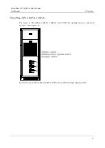
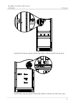
The UPS can equip the SNMP card, which can achieve the remote monitor for the input voltage and
frequency, output voltage and frequency, load, etc. of the UPS and remote ON/OFF operation. SNMP
card position is as shown in Figure2-21, Figure2-22 and Figure2-23.

