3 Installation
Three-Phase UPS (10kVA-160kVA) Series
User Manual
54
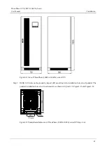
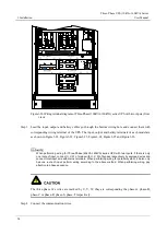
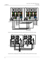
Figure3-26
Wiring terminal diagram of Three-Phase (100kVA-160kVA) series UPS with two inputs (front
view)
Step 3
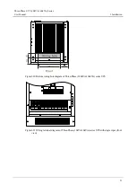
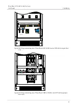
Lead the input, output and battery cables go through the bottom wiring hole and connect them with
corresponding wiring terminal of the UPS. The input, output and battery terminals of each model are
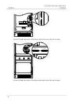
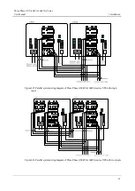
as shown in Figure3-21, Figure3-22, Figure3-23, Figure3-24, Figure3-25 and Figure3-26.
When performing wiring for Three-Phase (40kVA-160kVA) series UPS with two inputs, if there is only
one route of input, connect U, V, W of mains with U, V, W of bypass respectively by equipped wires and
connect total input wire with mains terminals. When performing wiring for parallel system, if it also only
has one route of input, perform wiring according to the above method. When performing wiring, pay
attention to phase sequence.
The three-phase live wires are marked by U, V, W, they are corresponding the phase-A, phase-B,
phase-C or phase-R, phase-S, phase-T respectively.
Step 4
Connect the communication wires.

