background image

7

1-855-GRN-RYDE  

(1-855-476-7933)

www.greenlightcycle.com

USER MANUAL - URBAN RYDER™ 

ASSEMBLE THE BIKE: FRONT WHEEL  

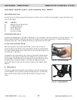
To tighten the Quick Release and axel into the fork dropout, ensure the Quick 

Release is in the open position with the lever parallel to the ground (the lever 

should be at a 90° angle to the forks).  With the lever in this position, tighten 

the round nut finger tight.  You will not be able to close the lever to the locked 

position yet.

Next, loosen the nut approximately 3 quarter turns (counter clockwise) and lift 

the lever upward to lock the wheel in place.  The lever should be almost parallel 

to the front fork when locked.  If the tension is correct, the lever should close 

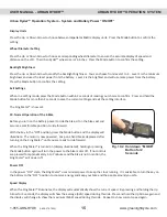
tightly.  When closing the lever it should leave a clear imprint in the palm of 

your hand (the imprint may not be as deep as the hand model’s picture).

When the lever is locked in this position (parallel to the fork), it will not easily 

be opened if it catches on any objects while riding your bike.  To increase or 

decrease the tension, open the lever and adjust the nut clockwise or counter 

clockwise, 1/8 turn at a time.  Repeat until the tension is sufficient.  Less than 

1/2 a turn on the adjusting nut can make the difference between safe clamping 

force and unsafe clamping force.   

Assemble the Bike: Front Wheel

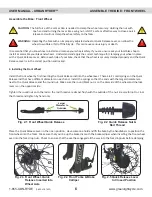
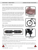
Fig. 2.7  Forks Secured Onto 

Front Wheel

Fig. 2.6  Imprint of Quick 

Release Lever After 

Correctly Closed

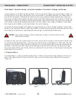
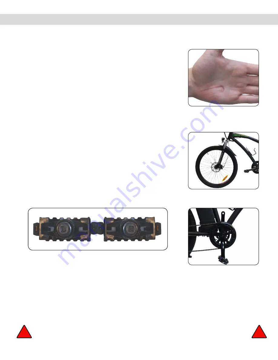
Fig. 3.2  Crank Arm, Right 

Pedal Inserted

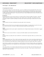
Fig. 3.1  Left & Right Pedals

3. Pedal Installation

Note:

 “L” and “R” (“L”=left & “R”=right) is stamped on the threaded ends of the 

pedals.  The pedals have opposite thread directions and must go on a specific 

side of the bike.  Left and right side of the bike is determined by sitting on the 

seat.

The

 Left Pedal

 has a reverse, non-standard thread and must be turned counter 

clockwise to be screwed in.
The 

Right Pedal

 has a standard thread and must be turned clockwise to be threaded in.

Apply some grease to the pedal threads before attaching.  Install the Right Pedal to the chain sprocket side of the bike and 

the Left Pedal to the opposite side (same side as the battery key).

Start the pedal threads into the crank arm threads, by hand, at least 4 complete 360° turns to ensure the pedals are not 

cross-threaded.  Incorrect installation of the pedals is not covered under warranty.  Complete by securely tightening with a 

15mm wrench.

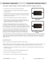
WARNING

:  

Poorly tightened pedals can result in injury or death.

!

!

Summary of Contents for Urban Cruzer

Page 1: ...exercised when operating the Urban Ryder Carefully read the following information even if you are an experienced rider wear a helmet and safety equipment and obey all Provincial and Federal motor vehi...

Page 2: ...er 14 Time Setting 14 Top Riding Speed 14 Display Units 15 Wheel Diameter Setting 15 Backlight Brightness 15 Exit Settings 15 Normal Operation of E Bike 15 Power OFF 15 Speed Display 15 Pedal Assist L...

Page 3: ...Lever 11 Handlebar 12 Frame 13 Seat Post 14 Quick Release Seat Lock 15 Seat 16 Battery Key 17 Battery 18 Rear Fender 19 Rear Brake Calliper 20 Tektro Rear Disc Brake 21 Shimano Freewheel 22 Hub Motor...

Page 4: ...ool Kit 5 x Hex Wrenches 2mm 3mm 4mm 5mm 6mm 3 x Wrenches double sided 8mm 10mm 13mm 15mm 14mm 17mm 1 x Screwdriver double sided star slot configuration 1 x King Meter Owner s Manual 1 x Shimano Gear...

Page 5: ...t out Replace the faceplate and tighten the bolts evenly so that the faceplate sits flat over the handlebar Fig 1 1 Handlebars Fig 1 2 Handlebar Stem Cut out Fig 1 3 Handlebar Stem With Handlebar Inse...

Page 6: ...e side Tighten the round nut onto the rod so the rod threads are almost flush with the outside of the nut Be careful not to cross the threads and tighten by hand only Place the Quick Release Lever in...

Page 7: ...at until the tension is sufficient Less than 1 2 a turn on the adjusting nut can make the difference between safe clamping force and unsafe clamping force Assemble the Bike Front Wheel Fig 2 7 Forks S...

Page 8: ...ease Lever up to the locked position Grab the seat by the saddle with both hands to attempt to rotate the seat If you are unable to force the seat out of alignment with the frame the clamp is tight en...

Page 9: ...Remove the key before trying to lift the battery away from the bike Remove the seat or turn it sideways to slide the battery straight up and out of the cradle using one hand on the folding handle and...

Page 10: ...batteries in extreme temperatures hot or cold and keep in a cool dry place Always plug the battery charger into a grounded ELECTRICAL circuit The battery can be used in any weather between 1 C to 38 C...

Page 11: ...to 185 F 85 C during normal charging Never enclose the charger or put anything on top of it when charging The charger must be well ventilated Fig 7 4 Battery Charged Green LED Fig 7 5 Battery Chargin...

Page 12: ...minute power from your battery Charge the battery frequently If possible before using 50 of the power When starting from dead stop use the pedals to bring the bike up to speed When riding uphill or a...

Page 13: ...up down arrows and mode button controls the E Bike s power ON OFF programming the display and settings 8 Power Up Your E Bike To turn on the bike battery turn the key on the battery to the ON positio...

Page 14: ...SSIST to 0 While Programming After LCD display lights up hold the UP and DOWN arrows at the same time for 3 seconds the LCD will display the default setting mode Time Setting After entering into the s...

Page 15: ...Seconds 10 Normal Operation of the E Bike Before you turn on the battery power to ride the bike sit on the bike seat and assume a comfortable position to ride forward With the key in the ON position p...

Page 16: ...11 2 Backlight Bike Headlight Hold down MODE UP Arrow Button for 3 Seconds Fig 11 1 Thumb Throttle Fig 11 3 King Meter Display Set ASSIST to 0 While Programming King Meter Display Backlight and Bike H...

Page 17: ...Thumb Throttle 12 Pedal Assist and Thumb Throttle With the King Meter illuminated and ASSIST set from Level 1 to 5 the thumb throttle is active When pressed downward the bike will drive forward The th...

Page 18: ...Drive the bike forward Headlight LED light controlled by pressing the Mode and Up Arrow buttons at the same time Bike Keys turns the battery electrical supply off on to the bicycle controls and locks...

Page 19: ...rider your first ride should be in an area without traffic or other hazards We suggest that you ride the bike as a bicycle with no power assist turned on set ASSIST to 0 to familiarize yourself with t...

Page 20: ...ck brake calliper is sticking closed Check battery is charged Wire is loose or disconnected at light LED s in head light are defective Check the wall receptacle move to another and retest Battery is f...

Page 21: ...hat 1 0mm on each side or up and down Wheels should only be adjusted by certified mechanics Spokes Check for damaged stainless spokes regularly Replace broken bent or fatigued stainless spokes with ma...

Page 22: ...g station Always use very little water and keep water away from the electrical contacts Check the plug in connections for moisture after cleaning and let these dry if necessary before using or chargin...

Page 23: ...harge FOB the Authorized Service Depot or the Factory making such repairs and is expressly limited to the replacement of goods complying with this warranty The company will not be responsible for any...

Page 24: ...anual for your own records To initiate your warranty please submit the following information online at www greenlightcycle com productregistration or mail a copy of this page to Urban Ryder Warranty R...

Reviews: